
Calculate a receiver noise floor and estimated sensitivity from bandwidth and noise figure, or from a known integrated noise floor.
Advanced options
Temperature and margin
Display
Table of contents
How to use our Receiver Noise Floor and Sensitivity Calculator
- Choose Start with: use bandwidth and noise figure for a model, or use a measured or specified integrated noise floor.
- For the model path, enter Noise bandwidth, select its Bandwidth unit, and enter Receiver noise figure.
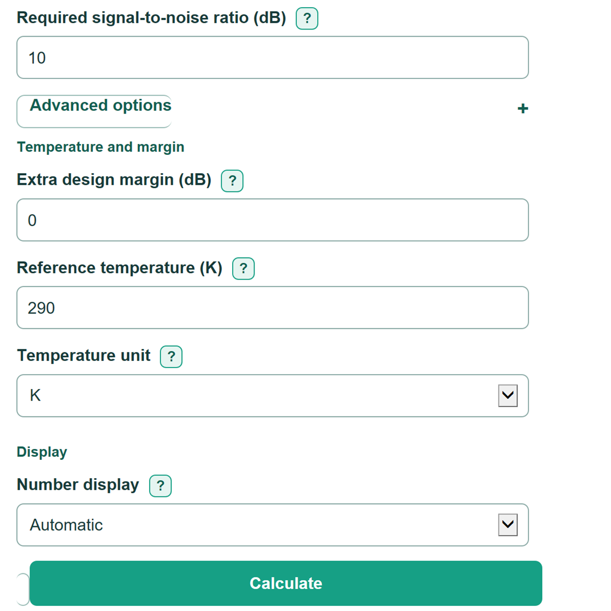
- Enter the Required signal-to-noise ratio from your radio, modem, test plan, or link budget.
- Open Advanced options only if needed to add Extra design margin (dB) or change the 290 K Reference temperature.
- Check that the receiver noise floor is plausible for your bandwidth, then use the estimated receiver sensitivity as the minimum input-power target for this simplified model.
Definitions
dBm: Power compared with 1 milliwatt. Negative dBm values are normal for receiver noise and weak signals.
Noise bandwidth: The bandwidth over which receiver noise is counted. Wider bandwidth passes more thermal noise.
Noise figure (dB): The amount a receiver adds above ideal thermal noise, stated in decibels.
Integrated noise floor: Total noise power over a stated bandwidth, expressed in dBm.
Noise density (dBm/Hz): Noise power per hertz. It is not the same as an integrated noise floor in dBm.
Signal-to-noise ratio (SNR): How far the signal must be above the noise floor, in dB, for the chosen system requirement.
Reference temperature: The physical temperature used in the thermal-noise calculation. The editable 290 K default is a conventional receiver reference condition. [1]
Common mistakes and quick fixes
Mistake: Entering 20 as Noise bandwidth while leaving Bandwidth unit set to MHz when the source says 20 kHz.
Fix: Select the unit printed beside the copied bandwidth before calculating.
Mistake: Putting a dBm/Hz noise density into Known integrated noise floor (dBm).
Fix: Use this field only for noise power already integrated over the relevant bandwidth in dBm.
Mistake: Using SINAD or Eb/N0 as Required signal-to-noise ratio (dB) without a documented conversion.
Fix: Enter an SNR requirement for the selected bandwidth, or convert the requirement outside this calculator using the system details.
Mistake: Adding a safety allowance to both Required signal-to-noise ratio (dB) and Extra design margin (dB).
Fix: Put the allowance in one place only; leave Extra design margin at 0 if the SNR already includes it.
Mistake: Treating the default Reference temperature as the receiver's actual operating temperature.
Fix: Keep 290 K for the conventional reference model, or enter the test or physical temperature with the matching temperature unit.
Limitations & Key Assumptions / Boundary Conditions
- This is a thermal-noise estimate. It does not model interference, adjacent-channel signals, oscillator phase noise, impulsive noise, fading, antenna losses, or receiver gain compression.
- The derived path assumes the entered Receiver noise figure is input-referred for the complete receiver chain and applies to the entered Noise bandwidth.
- Analyzer RBW is not always the receiver's equivalent noise bandwidth. Use RBW only when it matches the measurement situation you intend to estimate.
- Estimated receiver sensitivity is a power threshold based on the entered SNR and margin. It is not a BER, PER, SINAD, MDS, or regulatory certification result.
- The known-floor path accepts integrated dBm only. A dBm/Hz density must be integrated over the applicable bandwidth before it can be used as a known noise floor.
- Temperature affects only the derived thermal-noise path. The known-floor path uses the entered integrated noise floor directly.
Methodology
Calculation method
For the bandwidth-and-noise-figure path, the calculator converts bandwidth to Hz and temperature to K. It uses Boltzmann's constant, 1.380649e-23 J/K, to find ideal thermal noise. The 290 K default is an editable conventional receiver reference condition. [1]
N0_dBm_per_Hz = 10 * log10(k * T_K / 0.001)
N_dBm = N0_dBm_per_Hz + 10 * log10(B_Hz)
noise_floor_dBm = N_dBm + noise_figure_dB
For the known-noise-floor path, the entered integrated dBm value becomes the receiver noise floor directly. The calculator does not use bandwidth, noise figure, or temperature on that path.
sensitivity_dBm = noise_floor_dBm + required_SNR_dB + margin_dB
sensitivity_W = 0.001 * 10^(sensitivity_dBm / 10)
Worked example
At 290 K, 20 kHz bandwidth has ideal thermal noise of about -131.0 dBm. Adding a 5 dB receiver noise figure gives about -126.0 dBm. Adding 10 dB required SNR and 2 dB extra design margin gives estimated sensitivity of about -114.0 dBm.
Model conditions
Bandwidth must be greater than zero, and converted temperature must be above 0 K. A blank Extra design margin is treated as 0 dB; invalid nonblank entries stop the calculation. The calculation uses SNR only, so other quality measures need a system-specific conversion before use.