
Enter your fiber route, connection events, and optical budget to estimate link loss and remaining design margin.
Fiber path
Connections and reserve
Advanced options
Loss assumptions
Test and overload checks
Calculation details
Table of contents
How to use our Fiber-Optic Link Budget and Loss Calculator
- Choose how you know the optical budget: enter an Available optical budget in dB, or use the exact optic data sheet values for Tx minimum output and Receiver sensitivity in dBm.
- Enter the routed cable distance in Installed fiber length, choose the matching Fiber-length unit, and select the listed Fiber and wavelength.
- Count each adapter joining two plugs as one Mated connector pairs entry, then enter the planned Fusion splices and Required engineering reserve.
- Open Advanced options if the path has mechanical splices, a splitter, WDM equipment, another passive component, a measured test result, or overload ratings.
- Check Remaining design margin: 0 dB or more passes the entered reserve. Review Largest estimated loss source and make sure the route length, event counts, and data-sheet loss values match the design.
Definitions
dB: Decibel, a relative unit used here for optical loss, budget, and margin.
dBm: Decibels referenced to 1 milliwatt, an absolute optical-power unit used for transmitter and receiver ratings.
Optical budget: The total loss an optic or system can allow. With optic levels, it is Tx minimum output minus receiver sensitivity.
Mated connector pair: Two fiber connector plugs joined through one adapter. It is one connection event, not two.
Fiber attenuation: Optical signal loss per distance, stated here in dB/km. It changes with fiber type and wavelength. [1]
Engineering reserve: Extra design margin held back for uncertainty, aging, repairs, or project requirements; it is not physical path loss.
Receiver sensitivity: The weakest received optical power at which the receiver meets its specified operating conditions.
Receiver maximum input: The strongest optical power the receiver can accept before an overload concern.
Common mistakes and quick fixes
Mistake: Entering a straight-line building distance as Installed fiber length.
Fix: Use the routed cable length, including risers, turns, and planned slack.
Mistake: Counting two plugs in one adapter as two Mated connector pairs.
Fix: Count the joined plugs and adapter as one mated pair.
Mistake: Treating Tx minimum output or Receiver sensitivity as a dB loss value.
Fix: Enter those absolute power ratings in dBm only when using the optic-level budget path.
Mistake: Leaving the default Fiber attenuation (dB/km) for a cable with a different specified value.
Fix: Copy the attenuation at the selected wavelength from the cable data sheet or project specification.
Mistake: Hiding splitter loss inside Required engineering reserve.
Fix: Enter the actual passive loss as Splitter loss for this path (dB) and keep reserve as a separate design allowance.
Mistake: Using Measured installed loss (dB) as the planned loss before testing.
Fix: Leave it blank until a matching insertion-loss test result is available, then use it as a comparison with the estimate.
Limitations & Key Assumptions / Boundary Conditions
- This is a planning calculation, not an installation acceptance test or a guarantee that a link will operate.
- The selected attenuation, connector-loss, and fusion-splice defaults are planning values. Replace them with the exact cable, component, optic, and project values when available.
- The calculation assumes loss increases linearly with installed fiber length at the entered dB/km coefficient.
- It adds only the events and fixed losses entered. Unlisted patching, WDM devices, splitters, bends, contamination, damaged connectors, or extra splices can change real loss.
- Measured installed loss is only comparable when its test wavelength, direction, method, and path match the planned link.
- The optional overload check is an estimate based on entered maximum transmitter output and receiver maximum input. It does not replace the exact optic data sheet or system design review.
- Maximum fiber length assumes the same event counts, fixed losses, attenuation, and engineering reserve. It shows N/A when fixed losses already use the allowance or attenuation is zero.
Methodology
Calculation method
The calculator first converts the entered installed route to kilometers. It then adds cable attenuation and each entered fixed path loss. Engineering reserve is added after physical loss so it stays separate from real component loss.
route_length_km = installed_length * unit_to_km
fiber_loss = route_length_km * fiber_attenuation
connector_loss = mated_pairs * loss_per_mated_pair
fusion_loss = fusion_splices * loss_per_fusion_splice
physical_loss = fiber_loss + connector_loss + fusion_loss + mechanical_loss + splitter_loss + other_component_loss
loss_including_reserve = physical_loss + engineering_reserve
For a direct budget, the available optical budget is the entered dB value. For the optic-level path, the calculator subtracts receiver sensitivity from Tx minimum output. Although both inputs are dBm, their difference is a dB budget.
available_optical_budget = available_budget
available_optical_budget = tx_min_output - rx_sensitivity
remaining_design_margin = available_optical_budget - loss_including_reserve
A remaining design margin of 0 dB or more passes the entered budget and reserve. A negative value is retained as the size of the shortfall.
Extra checks
The maximum route length holds the entered fixed losses and reserve constant, then solves the remaining allowance for cable length. It is unavailable when attenuation is zero or fixed losses plus reserve already use the budget.
maximum_length_km = (available_optical_budget - engineering_reserve - fixed_losses) / fiber_attenuation
When both optional overload ratings are supplied, the tool estimates maximum received power from Tx maximum output and physical loss. Positive overload headroom means the estimate is below the entered receiver maximum-input limit.
receiver_overload_headroom = rx_max_input - (tx_max_output - physical_loss)
If a measured result is entered, the signed comparison is measured installed loss minus planned physical loss. A positive result means the measurement is higher than the estimate.
measured_vs_planned_loss = measured_installed_loss - physical_loss
Worked example
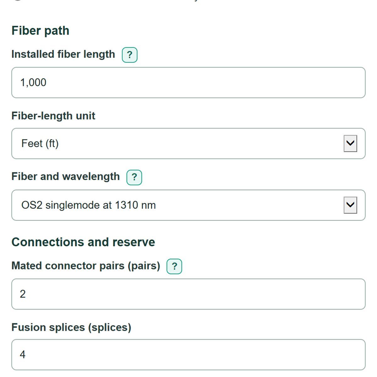
For 1,000 ft of OS2 fiber at 0.4 dB/km, the converted length is 0.3048 km and fiber loss is 0.12192 dB. With 2 mated pairs at 0.75 dB each and 4 fusion splices at 0.10 dB each, physical loss is 2.02192 dB. Adding a 3 dB reserve gives 5.02192 dB. Against a 10 dB available optical budget, remaining design margin is 4.97808 dB.
The planning coefficients associated with the fiber profiles, mated connections, and fusion splices are editable values based on FOA installation guidance; project specifications and exact data sheets take priority. [1] [2]