
Estimate a planning cable size for the DC battery cable between your battery bank and inverter.
Table of contents
How to use our Inverter Cable Size Calculator
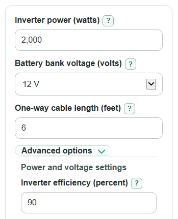
- Enter Inverter power (watts) using the inverter continuous rating, not the short surge rating.
- Pick Battery bank voltage (volts) and enter the One-way cable length (feet) from the battery positive terminal to the inverter positive terminal.
- Open Advanced options only if you want to change Inverter efficiency (percent), Max voltage drop (percent), Cable material, or Extra current cushion (percent).
- Select Calculate, then read Recommended cable size first and What made the size this big to see whether distance, current, or both controlled the answer.
- Sanity-check the result: Voltage lost in the cable should be at or below your Max voltage drop (percent), and Power turned into cable heat should not seem high for your setup.
Definitions
DC: Direct current, the type of electricity coming from a battery bank.
Voltage drop: Voltage lost as current moves through the cable. Less drop means the inverter receives more of the battery voltage.
AWG: American Wire Gauge, a US wire size system where smaller gauge numbers mean thicker wire.
kcmil: Thousand circular mils, a wire area unit used for large conductors bigger than common AWG sizes.
Circular mils: A wire area unit used in conductor tables. A larger circular mil value means a larger conductor area.
One-way cable length: The distance from the battery positive terminal to the inverter positive terminal. The calculator doubles it for the return path.
Inverter efficiency: The percent of battery power that becomes AC output power. Lower efficiency means more battery current for the same inverter watts.
75 C current heat check: A planning check that compares the design current with a 75 C ampacity value, which is a current limit for conductor heating.
Common mistakes and quick fixes
Mistake: Using surge watts in Inverter power (watts).
Fix: Use the inverter continuous watt rating so Battery current at full load is not overstated.
Mistake: Entering the full out-and-back cable run in One-way cable length (feet).
Fix: Enter only the one-way distance; the calculation already doubles it for the positive and negative cable path.
Mistake: Leaving Battery bank voltage (volts) at 12 V when the battery bank is really 24 V or 48 V.
Fix: Pick the actual DC battery voltage feeding the inverter before reading Recommended cable size.
Mistake: Setting Max voltage drop (percent) too high just to get a smaller wire.
Fix: Use a realistic limit, such as the value your inverter manual or installer wants, then check Voltage lost in the cable.
Mistake: Choosing Cable material as Aluminum when the inverter terminals require copper.
Fix: Confirm the inverter manual and terminals allow aluminum before using an aluminum Recommended cable size.
Mistake: Treating Extra current cushion (percent) as a fuse size setting.
Fix: Use Extra current cushion (percent) only for the heat check; size fuses or breakers from the inverter manual and local code.
Limitations & Key Assumptions / Boundary Conditions
- This is a planning calculator for the DC battery cable between a battery bank and an inverter. It does not size AC wiring.
- The recommended size is the smallest loaded size through 500 kcmil that passes both the voltage drop check and the 75 C current heat check.
- The loaded table may not match every cable type, insulation rating, temperature, conduit fill, terminal temperature rating, or installation rule.
- Aluminum results need extra care. Many inverter manuals and terminals require copper or special lugs.
- The calculator does not size fuses, breakers, disconnects, bus bars, lugs, or battery terminals. Follow the inverter manual and local code for overcurrent protection.
- Actual voltage at the inverter can also be affected by battery condition, state of charge, connection quality, and cable temperature.
- If no loaded size passes through 500 kcmil, reduce cable length, raise battery voltage, use a smaller inverter, or ask a qualified installer about a design outside this table.
Methodology
What the calculator checks
The calculator estimates full-load battery current from Inverter power (watts), Battery bank voltage (volts), and Inverter efficiency (percent). It then tests standard conductor sizes from 8 AWG through 500 kcmil. A size must pass both checks: voltage drop must be no more than Max voltage drop (percent), and the 75 C ampacity value must be at least the Current used for the heat check.
dc_current_a = inverter_power_w / (battery_voltage_v * (inverter_efficiency_percent / 100))
design_current_a = dc_current_a * (1 + current_margin_percent / 100)
allowed_drop_v = battery_voltage_v * (max_voltage_drop_percent / 100)
Voltage drop is calculated across the positive and negative cable path together, so the one-way length is multiplied by 2 [1].
voltage_drop_v = dc_current_a * resistance_ohm_per_1000ft * (2 * one_way_length_ft) / 1000
voltage_drop_percent = 100 * voltage_drop_v / battery_voltage_v
power_loss_w = dc_current_a * dc_current_a * resistance_ohm_per_1000ft * (2 * one_way_length_ft) / 1000
recommended_size = first size in size_table where ampacity_75c_a >= design_current_a and voltage_drop_percent <= max_voltage_drop_percent
How the controlling check is chosen
After the first passing size is found, the calculator looks at the next smaller loaded size. If that smaller size fails only the voltage drop test, What made the size this big is voltage drop. If it fails only the current heat test, the answer is current heat. If it fails both, the answer is both. If the recommended size is the smallest loaded size, the wording is conservative because there is no smaller loaded size to compare.
Mini-example
For a 2000 W inverter on a 12 V battery bank, 90% efficiency, 6 feet one-way copper cable, and 3% max voltage drop, the battery current is 2000 / (12 * 0.90) = 185.19 A. The smallest loaded copper size that passes both checks is 3/0 AWG, with 167800 circular mils, about 1.42% voltage drop, and about 31.52 W turned into cable heat.