
Find a buildable MOSFET gate resistor from gate charge, driver voltage, switching time, frequency, and peak driver current.
Advanced options
Table of contents
How to use our MOSFET Gate Resistor Calculator
- Enter Total gate charge Qg (nC) from the MOSFET data sheet at the same gate drive voltage you plan to use.
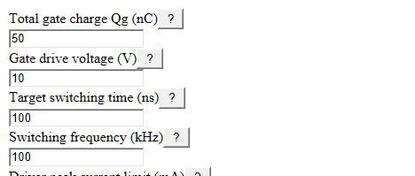
- Enter Gate drive voltage (V), Target switching time (ns), Switching frequency (kHz), and Driver peak current limit (mA).
- Open Advanced options if you know Driver output resistance (ohms), MOSFET internal gate resistance (ohms), or want a different Resistor choice.
- Select Calculate and read Recommended external gate resistor first, then check What set the result and Peak gate current.
- Sanity-check the result: if Estimated switching time with this resistor is much slower than your target, you may need a stronger driver, lower Qg MOSFET, or slower switching goal.
Definitions
Total gate charge Qg (nC): The charge needed to move the MOSFET gate through one switching edge, measured in nanocoulombs.
Gate drive voltage (V): The gate-to-source voltage applied by the driver, such as 5 V, 10 V, or 12 V.
Target switching time (ns): The desired time for one turn-on or turn-off edge, measured in nanoseconds.
Driver peak current limit (mA): The largest short pulse of current the gate driver should source or sink, measured in milliamps.
Driver output resistance (ohms): The resistance inside the driver output path during switching.
MOSFET internal gate resistance (ohms): The resistance already inside the MOSFET gate connection.
Resistor choice: The rounding rule for the external resistor: exact, E12 common 10% values, or E24 common 5% values.
Peak gate current: The estimated first current pulse into or out of the MOSFET gate in this resistance model.
Estimated gate-drive power: The average power used to charge and discharge the MOSFET gate at the selected switching frequency.
Common mistakes and quick fixes
Mistake: Using Total gate charge Qg (nC) from a data-sheet row measured at a different gate voltage.
Fix: Use the Qg value closest to your Gate drive voltage (V), or expect the result to be only a rough starting point.
Mistake: Entering the full PWM period as Target switching time (ns).
Fix: Enter the time for one turn-on or turn-off edge, not the time for a full on-off cycle.
Mistake: Putting the average driver current into Driver peak current limit (mA).
Fix: Use the source or sink peak current limit; if they differ, use the smaller value for one shared gate resistor.
Mistake: Leaving Driver output resistance (ohms) and MOSFET internal gate resistance (ohms) at guesses when the data sheets give better values.
Fix: Enter the data-sheet values, or use 0 ohms only when you want the simpler ideal-driver estimate.
Mistake: Picking Exact calculated value under Resistor choice and then installing a lower nearby resistor.
Fix: Use E12 - common 10% values or E24 - common 5% values so Recommended external gate resistor rounds up to a buildable value.
Mistake: Entering Switching frequency (kHz) in hertz.
Fix: Divide hertz by 1000 before entering it, because Estimated gate-drive power uses kHz.
Limitations & Key Assumptions / Boundary Conditions
- This is a first-pass gate-charge calculation. It does not replace checking the real gate waveform with an oscilloscope.
- Total gate charge Qg (nC) depends on MOSFET data-sheet test conditions, including gate voltage, drain voltage, drain current, and temperature.
- The model treats one shared resistor for turn-on and turn-off. If your circuit has separate paths, run the calculation for each path using the matching driver limit.
- It does not model the Miller plateau shape, nonlinear capacitance, PCB trace inductance, ringing, EMI, or gate-driver current limiting during the pulse.
- Rounding up to E12 or E24 keeps current lower, but it can make Estimated switching time with this resistor slower than the target.
- Estimated heat in the external resistor assumes loss divides in proportion to series resistance. Real pulse heating also depends on resistor construction and layout.
- A very small or zero Recommended external gate resistor can still be risky in a real circuit if layout inductance, ringing, or driver stress is high.
Methodology
Core calculation
The calculator estimates the total gate-path resistance needed to move the entered charge in the target edge time. With volts, nanoseconds, and nanocoulombs, the units reduce directly to ohms because 1 V * 1 ns / 1 nC equals 1 ohm.
R_total_time = V_drive * t_target_ns / Qg_nC
It then subtracts the resistance already in the driver and MOSFET gate path to find the external resistor needed for the time target.
R_ext_time = R_total_time - R_driver - R_internal_gate
The driver current limit gives a separate minimum external resistor. The current limit entered in milliamps is converted to amps before this step.
R_ext_current_min = (V_drive / I_peak_limit_A) - R_driver - R_internal_gate
The raw external resistor is the largest of zero, the time-based value, and the current-limit value.
R_ext_raw = max(0, R_ext_time, R_ext_current_min)
If Resistor choice is exact, the recommended value is the raw value. If E12 or E24 is selected, the value is rounded up to the first value in that series at or above the raw value.
R_recommended = first_standard_value_at_or_above(R_ext_raw, selected_series)
After rounding, the calculator recomputes the switching time, peak gate current, total gate-drive power, and the estimated heat share in the external resistor.
t_actual_ns = Qg_nC * (R_recommended + R_driver + R_internal_gate) / V_drive
I_peak_A = V_drive / (R_recommended + R_driver + R_internal_gate)
P_gate_mW = Qg_nC * V_drive * f_kHz * 0.001
P_ext_mW = P_gate_mW * R_recommended / (R_recommended + R_driver + R_internal_gate)
Worked example
For 50 nC, 10 V, 100 ns, 100 kHz, 1000 mA, 2 ohms driver resistance, 1.5 ohms internal gate resistance, and E24 rounding, the time-based total resistance is 20 ohms. Subtracting the 3.5 ohms already in the path gives 16.5 ohms external. The current-limit minimum is 6.5 ohms, so the raw value stays 16.5 ohms. E24 rounding raises it to 18 ohms. The estimated switching time becomes 107.5 ns, peak gate current is about 0.465 A, estimated gate-drive power is 50 mW, and estimated heat in the external resistor is about 41.86 mW.
Checks in the math
The calculator blocks zero or negative Total gate charge Qg (nC), Gate drive voltage (V), Target switching time (ns), and Driver peak current limit (mA). Switching frequency (kHz) may be zero, which makes gate-drive power zero. Optional resistance values must be 0 ohms or more. If the current-limit resistor is larger than the time-target resistor, What set the result reports that the driver current limit controls the answer and Important note explains that the target switching time cannot be met with that current limit.