
Calculate the DC Q-point for an NPN common-emitter BJT and check how beta changes the bias.
Table of contents
How to use our BJT Bias Calculator
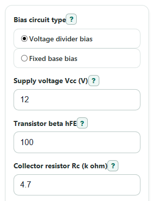
- Choose Bias circuit type: Voltage divider bias uses R1 and R2, while Fixed base bias uses Rb.
- Enter Supply voltage Vcc, Transistor beta hFE, Collector resistor Rc, and Emitter resistor Re in the units shown.
- Enter Top divider resistor R1 and Bottom divider resistor R2 for divider mode, or Base resistor Rb for fixed base mode.
- Open Advanced options if you want to change Base-emitter voltage Vbe, Saturation voltage Vce(sat), Low beta to check, or High beta to check.
- Click Calculate, then sanity-check Likely transistor region, Collector-emitter voltage Vce, and Current change across beta range before using the numbers in a build.
Definitions
BJT: A bipolar junction transistor. This calculator uses an NPN common-emitter DC model.
Q-point: The quiet DC operating point before any signal is added. It is described by current, voltage, and region.
Transistor beta hFE: The DC current gain. In active mode, collector current is beta times base current.
Vcc: The positive DC supply voltage feeding the collector resistor and bias network.
Vbe: The base-emitter voltage when the transistor is on. The default 0.7 V is a common silicon estimate, not a fixed constant.
Vce(sat): The collector-emitter voltage used as the saturation boundary. The default 0.2 V is an estimate and can change by transistor and current.
Thevenin values: A voltage source and resistance that replace the base resistor network for easier base-loop math. The equivalent resistance is found from the resistance seen at the output terminals with independent sources handled by the method [3].
Cutoff, active mode, saturation: Cutoff means the transistor is off, active mode is usually used for linear amplifiers, and saturation means the transistor is driven fully on like a switch.
Divider strength ratio: In voltage divider mode, this compares lower divider current to base current. A larger ratio means base current disturbs the divider less.
Common mistakes and quick fixes
Mistake: Entering Collector resistor Rc in ohms instead of k ohm.
Fix: Convert first; 4700 ohms should be entered as 4.7 for Collector resistor Rc.
Mistake: Leaving Top divider resistor R1 or Bottom divider resistor R2 in place after switching Bias circuit type to fixed base.
Fix: In fixed base mode, use Base resistor Rb; the divider resistor values are ignored.
Mistake: Treating Transistor beta hFE as an exact value.
Fix: Use Low beta to check and High beta to check to see whether Collector current Ic changes too much.
Mistake: Reading an active-mode answer after Likely transistor region says saturation.
Fix: Use the displayed Collector current Ic and Collector-emitter voltage Vce from the saturation model, not the active-mode estimate from hand math.
Mistake: Setting Emitter resistor Re to 0 by accident.
Fix: Use 0 only if the circuit truly has no emitter resistor; otherwise enter the real Emitter resistor Re value in k ohm.
Mistake: Keeping the default Base-emitter voltage Vbe or Saturation voltage Vce(sat) when your datasheet gives different values.
Fix: Update Base-emitter voltage Vbe and Saturation voltage Vce(sat) in Advanced options when accuracy matters.
Limitations & Key Assumptions / Boundary Conditions
- This calculator is for NPN common-emitter DC bias only. It does not design AC gain, input impedance, output impedance, capacitors, or frequency response.
- The model uses resistor DC values and ideal supply voltage. Real resistor tolerance, supply tolerance, temperature, and transistor heating can move the Q-point.
- Base-emitter voltage Vbe and saturation voltage Vce(sat) are treated as user-entered constants, even though real values change with current and temperature.
- Leakage current is ignored in cutoff, so very high-resistance or high-temperature circuits may differ from the result.
- When the active-mode estimate falls at or below Saturation voltage Vce(sat), the calculator switches to the saturation model and beta no longer directly sets Collector current Ic.
- The beta range check is a sensitivity check, not a pass-fail rule. A good range depends on the circuit purpose and allowed signal swing.
- If Emitter resistor Re is 0, there is little or no emitter feedback, so fixed base circuits can become very sensitive to Transistor beta hFE.
Methodology
Base network setup
The calculator first replaces the base bias network with a Thevenin source so voltage divider bias and fixed base bias can use the same base-loop equations. Voltage divider bias is commonly used to reduce beta dependence in common-emitter bias circuits [1].
Vth = Vcc * R2 / (R1 + R2)
Rth = (R1 * R2) / (R1 + R2)
For fixed base bias, the same model is simpler.
Vth = Vcc
Rth = Rb
Region logic
If the Thevenin voltage is not high enough to forward-bias the base-emitter junction, the calculator reports cutoff.
Ib = 0; Ic = 0; Ie = 0; Ve = 0; Vb = Vth; Vc = Vcc; Vce = Vcc
If Vth is greater than Vbe, the calculator first tries the active-mode equations.
Ib = (Vth - Vbe) / (Rth + (beta + 1) * Re)
Ic = beta * Ib
Ie = (beta + 1) * Ib
Ve = Ie * Re
Vb = Ve + Vbe
Vc = Vcc - Ic * Rc
Vce = Vc - Ve
If that active-mode estimate gives Vce at or below Vce(sat), the calculator changes to the saturation equations instead of showing an impossible beta-limited collector current. A transistor bias point may be described as cutoff, active operation, or saturation [2].
A = 1 / Rc
B = 1 / Rth
C = Vcc - Vcesat
D = Vth - Vbe
Ve = Re * (A * C + B * D) / (1 + Re * (A + B))
Ic = A * (C - Ve)
Ib = B * (D - Ve)
Ie = Ic + Ib
Vb = Ve + Vbe
Vc = Ve + Vcesat
Vce = Vcesat
Beta and divider checks
For voltage divider mode, the divider strength ratio compares the lower divider current with base current. If base current is zero, the ratio is shown as N/A to avoid division by zero.
divider_strength_ratio = (Vb / R2) / Ib
The calculator also runs the same region logic at Low beta to check and High beta to check.
beta_current_change_percent = 100 * (Ic_high - Ic_low) / Ic_low
Mini-example
With Voltage divider bias, Vcc = 12 V, beta = 100, Rc = 4.7 k ohm, Re = 1 k ohm, R1 = 47 k ohm, R2 = 10 k ohm, Vbe = 0.7 V, and Vce(sat) = 0.2 V, the active-mode calculation gives about Ic = 1.286 mA, Vc = 5.954 V, Ve = 1.299 V, and Vce = 4.655 V. Since 4.655 V is greater than 0.2 V, the likely region is active mode.
Unit handling
All resistor entries in k ohm are multiplied by 1000 before calculation. Collector current is shown in mA by multiplying amps by 1000, and base current is shown in microamps by multiplying amps by 1000000.