
Calculate a practical BJT base resistor for an on/off transistor switch and check the pin current and resistor power.
Advanced options
Table of contents
How to use our Transistor Base Resistor Calculator
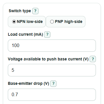
- Choose the Switch type that matches your circuit: NPN low-side for a load above the transistor, or PNP high-side for a transistor above the load.
- Enter Load current, Voltage available to push base current, Base-emitter drop, and Collector-to-base current ratio using the same circuit conditions you plan to build.
- Open Advanced options if you want to change the Standard resistor series or check a Control pin current limit and Base resistor power rating.
- Click Calculate, then use Recommended base resistor if Control pin current margin and Base resistor power margin are positive or if the optional checks are left blank.
- Sanity-check the result: Base current with the recommended resistor should be at least Needed base current, and any Check note should be fixed before building the circuit.
Definitions
BJT: A bipolar junction transistor. In this calculator, it is used as an on/off switch, not as an audio or analog amplifier.
Base resistor: The resistor in series with the transistor base. It limits base current so the control pin and transistor are not overloaded [3].
NPN low-side: A common switch setup where the load connects to positive supply and the NPN transistor connects the load to ground when on.
PNP high-side: A switch setup where the PNP transistor sits between the positive supply and the load, and turns on when its base is pulled lower than its emitter.
Load current: The collector current the transistor must switch, entered in milliamps.
Voltage available to push base current: The voltage that drives current through the base resistor before the Base-emitter drop is subtracted.
Base-emitter drop: The voltage used up across the transistor's base-emitter junction while current flows into the base.
Collector-to-base current ratio: Load current divided by planned base current. A smaller ratio gives more base current.
Standard resistor series: The real-world resistor value set, such as E12, E24, or E96, used to round the exact maximum resistor down to a buyable value.
Control pin current margin: Control pin current limit minus Base current with the recommended resistor. Positive is under the limit; negative is over the limit.
Common mistakes and quick fixes
Mistake: Using the power supply voltage as Voltage available to push base current when the control pin is not at that voltage.
Fix: Use the voltage that is actually across the base resistor before subtracting Base-emitter drop.
Mistake: Entering the load's supply voltage in Load current instead of the load current in mA.
Fix: Find or measure the running current of the load, then enter that number as Load current.
Mistake: Setting Collector-to-base current ratio equal to the transistor's advertised gain.
Fix: For switching, use a forced ratio such as 10 to start unless your datasheet gives a better saturation test value.
Mistake: Ignoring a negative Control pin current margin because the Recommended base resistor still appears.
Fix: A negative Control pin current margin means the pin limit is exceeded; raise the resistor only if the transistor still gets enough base current, or use a driver stage.
Mistake: Choosing a tiny resistor without checking Power in the base resistor.
Fix: Compare Power in the base resistor with Base resistor power rating and use a higher wattage part if the margin is negative.
Limitations & Key Assumptions / Boundary Conditions
- This calculator is for saturated BJT switch estimates. It does not design amplifier bias networks, audio stages, MOSFET gates, Darlington drivers, optocouplers, or current mirrors.
- The result depends strongly on the entered Base-emitter drop and Collector-to-base current ratio. Use datasheet saturation values when you have them.
- The transistor itself still needs separate checks for maximum collector current, voltage rating, package heating, and safe operating area.
- Inductive loads such as relays, motors, and solenoids usually need flyback protection. This calculator does not size that diode or snubber.
- Control pin current limits vary by microcontroller, by total chip current, and by voltage. Enter the limit from your board or chip datasheet.
- Rounding chooses the largest standard resistor not above the exact maximum. If you use a lower value, base current and resistor power will increase.
- Very high currents, very low voltages, unusual transistor types, and high-speed switching may need a more detailed design than this DC estimate.
Methodology
Switching idea
A BJT switch uses base current to let a larger collector current flow through the load. In a driver circuit, the logic pin supplies base current instead of the full load current [1]. The base resistor limits that base current [3].
Core formulas
Current is converted from milliamps to amps before using Ohm's law.
collector_current_A = load_current_mA / 1000
required_base_current_A = collector_current_A / forced_beta
resistor_voltage_V = drive_voltage_V - base_emitter_drop_V
exact_max_resistor_ohm = resistor_voltage_V / required_base_current_A
The recommended resistor is the largest E12, E24, or E96 standard value that is less than or equal to the exact maximum.
recommended_resistor_ohm = largest_standard_resistor_less_than_or_equal_to(exact_max_resistor_ohm)
actual_base_current_A = resistor_voltage_V / recommended_resistor_ohm
actual_base_current_mA = actual_base_current_A * 1000
If Control pin current limit is entered, the margin is kept signed so a negative value clearly means the design is over the entered limit.
pin_current_margin_mA = pin_max_current_mA - actual_base_current_mA
Resistor heat is calculated from current squared times resistance.
base_resistor_power_W = actual_base_current_A * actual_base_current_A * recommended_resistor_ohm
If Base resistor power rating is entered, the margin is also kept signed.
resistor_power_margin_W = resistor_power_rating_W - base_resistor_power_W
Mini-example
For a 100 mA load, 5 V drive, 0.7 V base-emitter drop, and a collector-to-base current ratio of 10, the needed base current is 10 mA. The resistor voltage is 4.3 V, so the exact maximum resistor is 4.3 V / 0.010 A = 430 ohm. With E24 selected, the recommended base resistor is 430 ohm, the actual base current is 10 mA, and the resistor power is 0.043 W.
Input checks
The calculator blocks results if Load current or Collector-to-base current ratio is not greater than zero, or if Voltage available to push base current is not greater than Base-emitter drop. Optional limits are checked only when entered.