
Calculate resonance, Q factor, bandwidth, half-power points, and optional impedance for an ideal series or parallel RLC circuit.
Table of contents
How to use our RLC Circuit Calculator
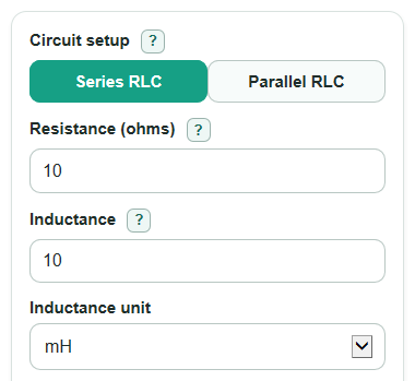
- Choose Circuit setup: Series RLC for one current path, or Parallel RLC when R, L, and C are separate branches across the same two nodes.
- Enter Resistance (ohms), Inductance with its Inductance unit, and Capacitance with its Capacitance unit.
- Open Advanced options only if you want Impedance at test frequency, Phase at test frequency, or Current at test frequency for a specific Test frequency.
- If you enter Source voltage (V RMS), use an RMS AC voltage; 0 is allowed and gives 0 current.
- Sanity-check the result: Resonant frequency should be between the Lower half-power frequency and Upper half-power frequency, and a larger Q factor should match a smaller Bandwidth.
Definitions
RLC circuit: A circuit made from a resistor R, inductor L, and capacitor C.
Series RLC: The resistor, inductor, and capacitor are in one path, so the same current flows through all three parts.
Parallel RLC: The resistor, inductor, and capacitor are separate branches across the same two nodes, so they share the same voltage.
Resonant frequency: The frequency where the inductor and capacitor cancel each other's reactance in the ideal model.
Q factor: A unitless number that tells how sharp the resonance is; higher Q means a narrower resonant band.
Bandwidth: The frequency width between the lower and upper half-power frequencies.
Half-power frequency: A band edge where the ideal circuit power is half of its peak value.
Impedance: The AC version of resistance, combining resistance and reactance in ohms.
Phase: The angle that tells whether the circuit acts more inductive or more capacitive at the test frequency.
V RMS: The usual effective AC voltage value used to compute AC current and power.
Common mistakes and quick fixes
Mistake: Choosing Series RLC in Circuit setup when the resistor is actually a shunt branch across the inductor and capacitor.
Fix: Use Parallel RLC for a resistor, inductor, and capacitor connected across the same two nodes.
Mistake: Entering the inductor's small winding resistance in Resistance (ohms) while Circuit setup is Parallel RLC.
Fix: Parallel RLC expects the shunt resistance across the tank, not the inductor's series resistance.
Mistake: Typing 100 for Capacitance but leaving Capacitance unit as uF when the part is 100 nF.
Fix: Match Capacitance unit to the part label before you trust Resonant frequency.
Mistake: Entering 10 for Inductance while Inductance unit is H when the part is 10 mH.
Fix: Set Inductance unit to mH, uH, nH, or H to match the value you typed.
Mistake: Entering Test frequency as 1 and Test frequency unit as Hz when you meant 1 kHz.
Fix: Use Test frequency unit to scale the value, so Impedance at test frequency and Phase at test frequency use the intended frequency.
Mistake: Expecting Current at test frequency when Source voltage (V RMS) is blank.
Fix: Enter Source voltage (V RMS) if you want current; leave it blank if you only need impedance and phase.
Limitations & Key Assumptions / Boundary Conditions
- The calculator uses ideal lumped parts. Real inductors, capacitors, leads, circuit boards, and meters can add extra resistance, capacitance, or inductance.
- Resistance (ohms) means total series resistance for Series RLC, but shunt resistance for Parallel RLC. Mixing these models can change Q factor, Bandwidth, and half-power points a lot.
- Inductance and Capacitance must be greater than 0. Resistance must be greater than 0 because the Q and bandwidth formulas divide by resistance or use 1 over resistance.
- Test frequency is optional, but if entered it must be greater than 0 because reactance formulas divide by frequency.
- Source voltage (V RMS) may be 0 or greater. Current at test frequency is shown only when both Test frequency and Source voltage (V RMS) are valid.
- At very low Q factor, resonance is broad. The half-power points can be far from the resonant frequency, so the circuit may not act like a narrow filter.
- The results do not include component tolerance, heating, saturation, dielectric loss, frequency-dependent resistance, or parasitic self-resonance.
Methodology
Unit conversion
The calculator first converts all entered values to base units: inductance in henries, capacitance in farads, and optional test frequency in hertz. SI prefixes such as milli, micro, nano, pico, kilo, and mega are applied as decimal multipliers.
L_H = inductance_value * inductance_unit_multiplier
C_F = capacitance_value * capacitance_unit_multiplier
f_Hz = test_frequency_value * frequency_unit_multiplier
Resonance, Q, and bandwidth
The ideal resonant frequency uses the same base formula for ideal series and parallel RLC circuits.
f0 = 1 / (2 * π * sqrt(L_H * C_F))
For Series RLC, Resistance (ohms) is treated as series resistance.
Q = (1 / R_ohms) * sqrt(L_H / C_F)
For Parallel RLC, Resistance (ohms) is treated as a shunt resistance across the tank.
Q = R_ohms * sqrt(C_F / L_H)
Bandwidth is the resonant frequency divided by Q factor.
bandwidth_hz = f0 / Q
Half-power points
For Series RLC, the exact ideal half-power frequencies are calculated from the series impedance model.
f1 = (sqrt(R_ohms^2 + 4 * L_H / C_F) - R_ohms) / (4 * π * L_H)
f2 = (sqrt(R_ohms^2 + 4 * L_H / C_F) + R_ohms) / (4 * π * L_H)
For Parallel RLC, the exact ideal half-power frequencies are calculated from the parallel admittance model.
f1 = (-1 / R_ohms + sqrt((1 / R_ohms)^2 + 4 * C_F / L_H)) / (4 * π * C_F)
f2 = (1 / R_ohms + sqrt((1 / R_ohms)^2 + 4 * C_F / L_H)) / (4 * π * C_F)
Optional test frequency check
When Test frequency is entered, the calculator also checks impedance and phase at that exact frequency. For Series RLC, it uses the standard AC impedance relationship between resistance, inductive reactance, and capacitive reactance [2].
XL = 2 * π * f_Hz * L_H
XC = 1 / (2 * π * f_Hz * C_F)
X = XL - XC
Z_mag = sqrt(R_ohms^2 + X^2)
phase_deg = atan2(X, R_ohms) * 180 / π
I_rms = V_rms / Z_mag
For Parallel RLC, the calculator works with admittance first, then converts to impedance magnitude.
G = 1 / R_ohms
B = 2 * π * f_Hz * C_F - 1 / (2 * π * f_Hz * L_H)
Y_mag = sqrt(G^2 + B^2)
Z_mag = 1 / Y_mag
phase_deg = -atan2(B, G) * 180 / π
I_rms = V_rms * Y_mag
A positive phase value means the circuit is net inductive. A negative phase value means it is net capacitive. Near 0 degrees means the circuit is mostly resistive at the test frequency.
Worked mini-example
With Series RLC, Resistance (ohms) = 10, Inductance = 10 mH, and Capacitance = 100 nF, the converted values are L_H = 0.01 H and C_F = 0.0000001 F. The calculator gives Resonant frequency about 5.033 kHz, Q factor about 31.62, Bandwidth about 159.15 Hz, Lower half-power frequency about 4.954 kHz, and Upper half-power frequency about 5.113 kHz. If Test frequency = 1000 Hz and Source voltage (V RMS) = 5, the series impedance is about 1528.75 ohms, phase is about -89.63 degrees, and current is about 0.00327 A RMS.