
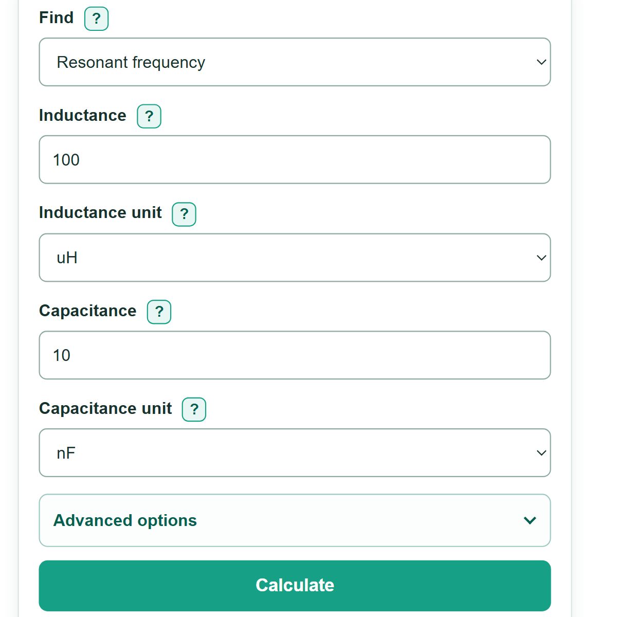
Enter two known LC values to calculate the ideal resonant frequency or find the inductance or capacitance needed for your target frequency.
Advanced options
This is the ideal lossless result. Real parts and wiring can shift the measured resonance.
Check the chosen part's tolerance, losses, and self-resonant frequency.
Check the chosen part's tolerance, ESR, ESL, and voltage rating.
This planning range uses the entered tolerance corners. It is not a guaranteed measured range.
Use this only when an equation asks for angular frequency.
Table of contents
How to use our LC Resonance Calculator
- Choose the unknown quantity in "Find."
- Enter the two known values and select the unit shown on the component marking, schematic, datasheet, or circuit requirement.
- Select "Calculate" to see the ideal resonant frequency or the needed component value.
- For a frequency calculation, open "Advanced options" and enter either part tolerance to estimate a tolerance-corner frequency range.
- Sanity-check the units before using the answer. A value in mH instead of uH, or pF instead of nF, can change resonance by a large amount.
Definitions
LC circuit: A circuit with an inductor and capacitor that exchange stored energy. It is also called a resonant circuit or tank circuit.
Inductance (L): An inductor's ability to store energy in a magnetic field. The base unit is the henry (H).
Capacitance (C): A capacitor's ability to store energy in an electric field. The base unit is the farad (F).
Resonant frequency: The frequency where ideal inductive and capacitive effects balance. This calculator reports ordinary frequency in Hz.
Angular frequency: Frequency in radians per second (rad/s). It equals 2 times pi times ordinary frequency in Hz.
Tolerance: The allowed percentage variation from a component's labeled value. The range uses the lowest and highest possible L and C values from the entered tolerances.
Engineering prefixes: m means milli (1/1,000), u means micro (1/1,000,000), n means nano (1/1,000,000,000), and p means pico (1/1,000,000,000,000).
Common mistakes and quick fixes
Mistake: Entering 100 and selecting mH when the inductor is marked 100 uH.
Fix: Copy both the number and prefix from the part marking, schematic, BOM, datasheet, or meter.
Mistake: Changing a unit selector after entering a number and expecting the number to convert.
Fix: The selector gives the entered number its unit. Convert or re-enter the number before changing the unit.
Mistake: Entering angular frequency in rad/s as if it were ordinary frequency in Hz.
Fix: Enter frequency in Hz, kHz, or MHz. Use the angular frequency result only in equations that require rad/s.
Mistake: Treating the nominal frequency as an exact measurement of a finished circuit.
Fix: Enter the actual inductor and capacitor tolerances for a component-only range, then account for wiring and part parasitics separately.
Mistake: Using resonant frequency as a filter cutoff frequency.
Fix: Use this calculator for ideal LC resonance. Cutoff frequency, bandwidth, and Q need the circuit topology and resistance.
Limitations & Key Assumptions / Boundary Conditions
- The calculation uses an ideal lossless LC model. Resistance, inductor core losses, capacitor ESR, capacitor ESL, wiring inductance, and stray capacitance can shift measured resonance.
- The tolerance range uses independent worst-case component-value corners. It is a planning range, not a guarantee of measured circuit behavior.
- Each entered tolerance must be from 0 up to, but not including, 100%. A blank tolerance counts as 0% only when the other tolerance is entered.
- The calculator does not calculate filter cutoff frequency, Q, bandwidth, impedance, voltage gain, power handling, or stability.
- A calculated value may not match a standard stocked component. Choose a nearby real part, then recalculate using its actual value and tolerance.
- At high frequencies, an inductor's self-resonant frequency and component parasitics can make the ideal equation unsuitable.
Methodology
Ideal LC equation
The calculator converts inductance to henries, capacitance to farads, and frequency to hertz before calculating. In the ideal equation, increasing either inductance or capacitance lowers the resonant frequency.
f = 1 / (2π√(LC))
In this equation, f is resonant frequency in Hz, L is inductance in H, and C is capacitance in F. When finding a missing part, the calculator rearranges the same equation.
L = 1 / ((2πf)^2 C)
C = 1 / ((2πf)^2 L)
Worked mini-example
For L = 100 uH and C = 10 nF, the converted values are 0.0001 H and 0.00000001 F. The ideal resonant frequency is about 159.2 kHz, and the angular frequency is 1,000,000 rad/s.
Tolerance calculation
When either optional tolerance is entered, the nominal frequency remains the main answer. The low-frequency corner uses the largest allowed inductance and capacitance. The high-frequency corner uses the smallest allowed values.
f_low = f_nominal / √((1 + L_tol/100)(1 + C_tol/100))
f_high = f_nominal / √((1 - L_tol/100)(1 - C_tol/100))