
Calculate inductive reactance, or work backward to find the needed inductance or frequency.
Table of contents
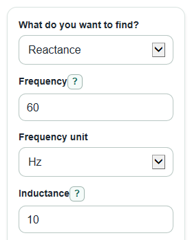
How to use our Inductive Reactance Calculator
- Choose What do you want to find?: Reactance, Inductance, or Frequency.
- Enter the known values and pick the correct Frequency unit and Inductance unit, such as Hz, kHz, H, mH, or uH.
- If you are solving for Inductance or Frequency, enter the target Reactance (ohms) instead of the missing value.
- Open Advanced options only if you want a current check from Applied voltage (V RMS) or a real-coil check from Coil resistance (ohms).
- Sanity-check the result: changing frequency or inductance 10 times larger should make Inductive reactance 10 times larger.
Definitions
Inductive reactance: The ideal inductor's opposition to AC current, measured in ohms. It increases when frequency or inductance increases [3].
Frequency: How many AC cycles happen each second. Hz means cycles per second, kHz means thousands of Hz, and MHz means millions of Hz.
Inductance: How strongly a coil stores energy in a magnetic field. It is measured in henries, written H.
Angular frequency: ω (angular frequency in rad/s) equals 2*pi times regular frequency. Some textbooks use it in the form XL = ωL.
RMS voltage: The AC voltage value normally used for power and Ohm's law style calculations, such as 120 V RMS wall power.
Coil resistance: The DC wire resistance of the inductor, often called DCR. It is separate from inductive reactance.
Current lag angle: The phase angle showing how far current lags behind voltage in the series coil model.
Common mistakes and quick fixes
Mistake: Entering 10 in Inductance but leaving Inductance unit on H when the part is 10 mH.
Fix: Set Inductance unit to mH, or enter 0.01 if you truly want H.
Mistake: Typing 100 for Frequency and choosing Hz when the source is 100 kHz.
Fix: Change Frequency unit to kHz, or enter 100000 with Hz.
Mistake: Using Reactance (ohms) as if it were Coil resistance (ohms).
Fix: Put the target AC pushback in Reactance (ohms), and put measured wire resistance in Coil resistance (ohms) only if you want the real-coil check.
Mistake: Leaving Reactance (ohms) blank after choosing Inductance or Frequency.
Fix: Enter the target reactance value because that mode works backward from the wanted ohms.
Mistake: Entering Applied voltage (V RMS) as peak voltage from a scope reading.
Fix: Convert to RMS first, or use an RMS meter value, so the Ideal inductor current is in A RMS.
Mistake: Treating Current with coil resistance as exact for every coil.
Fix: Use Coil resistance (ohms) as a simple series-resistance check, and remember it does not include core loss, saturation, or stray capacitance.
Limitations & Key Assumptions / Boundary Conditions
- The main XL result uses an ideal inductor model. Real inductors can also have winding resistance, core loss, saturation, and stray capacitance.
- The advanced real-coil check treats Coil resistance (ohms) as a simple series resistor with an ideal inductor.
- Applied voltage (V RMS) must be an RMS value. Peak, peak-to-peak, or pulse voltage values will not give the same current result.
- At 0 Hz, the ideal inductive reactance is 0 ohms after the switching moment is over, so ideal-only current from voltage would be undefined instead of useful.
- This calculator reports reactance magnitude as a nonnegative value. It does not track phasor signs or complex impedance notation.
- Results do not account for temperature changes, frequency-dependent resistance, inductor tolerance, magnetic core behavior, or self-resonance.
Methodology
Core calculation
Inductive reactance is calculated from frequency and inductance using the standard ideal-inductor formula [1]. Frequency is converted to hertz, and inductance is converted to henries before any formula is used.
XL = 2*pi*f*L
In this formula, XL is inductive reactance in ohms, f is frequency in Hz, and L is inductance in H. The calculator uses Math.PI for pi.
Working backward
When you choose Inductance, the calculator rearranges the same formula to solve for L.
L = XL / (2*pi*f)
When you choose Frequency, the calculator rearranges the same formula to solve for f.
f = XL / (2*pi*L)
The angular frequency output uses the textbook shortcut ω = 2*pi*f.
omega = 2*pi*f
Optional current and real-coil check
If Applied voltage (V RMS) is entered and XL is greater than 0, ideal current is found by dividing RMS voltage by inductive reactance [1].
Iideal = Vrms / XL
If Coil resistance (ohms) is entered, the calculator combines the resistance and reactance as a series coil impedance size.
Zmag = sqrt(Rcoil^2 + XL^2)
When both voltage and coil resistance are entered, current with coil resistance uses that impedance size.
Ireal = Vrms / Zmag
The current lag angle uses the arctangent of the reactance and resistance parts, then converts radians to degrees.
phase_degrees = atan2(XL, Rcoil) * 180 / pi
Mini-example
For 60 Hz and 10 mH, first convert 10 mH to 0.01 H. Then XL = 2*pi*60*0.01 = 3.7699 ohms, so the normal rounded result is about 3.77 ohms. The angular frequency is 2*pi*60 = 376.991 rad/s.
Sources
- 23.11 Reactance, Inductive and Capacitive - College Physics 2e - Openstax
- 3.2: AC Inductor Circuits - Workforce LibreTexts - Libretexts
- Reactance | Electronics, Psychology & Communication | Britannica - Encyclopedia Britannica
- AC inductor circuits : REACTANCE AND IMPEDANCE -- INDUCTIVE - Learningelectronics