
Calculate the real output voltage after a load is connected to a two-resistor voltage divider.
Table of contents
How to use our Voltage Divider Load Calculator
- Enter Input voltage Vin (V), Top resistor R1 (ohms), and Bottom resistor R2 (ohms).
- Enter Load resistance RL (ohms), or leave it blank if you want the no-load divider result only.
- Open Advanced options if you want a pass/fail check using Allowed output change (percent) or a heat check using Resistor power rating (W).
- Click Calculate and read Output voltage with the load first, then compare Output change from no load with your allowed change.
- Sanity-check the result: a smaller Load resistance RL (ohms) should pull the output farther from Output voltage with no load, while a much larger load should make the two voltages nearly match.
Definitions
Input voltage Vin: The voltage across the whole divider, from the top of R1 to ground.
Top resistor R1: The resistor between the input voltage and the output point.
Bottom resistor R2: The resistor between the output point and ground.
Load resistance RL: The resistance of the circuit connected to the output. In this model, it is placed in parallel with R2.
Parallel resistance: The smaller combined resistance made when two resistors connect across the same two points.
Output voltage with no load: The ideal divider voltage before the outside circuit draws current.
Output voltage with the load: The divider voltage after RL is connected.
Output resistance seen by the load: The Thevenin resistance of the divider, which shows how strongly the divider output can hold its voltage when a load is attached.
Allowed output change: The largest percent change from the no-load voltage that you are willing to accept.
Common mistakes and quick fixes
Mistake: Putting the sensor, chip input, or next circuit into Top resistor R1 (ohms) instead of Load resistance RL (ohms).
Fix: Enter the circuit connected to the output point as Load resistance RL (ohms), because it sits across Bottom resistor R2 (ohms).
Mistake: Leaving Load resistance RL (ohms) blank when a real circuit is attached.
Fix: Use the input resistance from the next circuit data sheet, or enter your best measured resistance so Output voltage with the load is realistic.
Mistake: Typing 10 for Top resistor R1 (ohms) when you mean 10,000 ohms.
Fix: Enter full ohms, such as 10000 or 10,000, not kilo-ohms.
Mistake: Treating Output change from no load as always positive.
Fix: Read the sign: negative means the load pulled Output voltage with the load lower than Output voltage with no load.
Mistake: Setting Allowed output change (percent) to 0 or 100.
Fix: Enter a value greater than 0 and less than 100, such as 1, 2, or 5.
Mistake: Ignoring Power in R1 and Power in R2 when Input voltage Vin (V) is high or resistor values are low.
Fix: Enter Resistor power rating (W) and check Power check before choosing real parts.
Limitations & Key Assumptions / Boundary Conditions
- This model treats R1, R2, and RL as fixed resistors. Real parts have tolerance, temperature drift, and possible nonlinear behavior.
- Load resistance RL is modeled as one resistor from the output point to ground. It does not model active loads, pulsed loads, capacitor charging, or changing input impedance.
- The calculator uses DC steady-state math. It does not include AC frequency effects, capacitor filters, wire resistance, or source resistance.
- Input voltage Vin (V) may be negative, and voltage and current outputs keep that sign. Power outputs are heat or delivered power, so they are never negative.
- If Output voltage with no load is 0 V, percent Output change from no load is not meaningful because it would divide by zero.
- Minimum load for your limit assumes the allowed change is greater than 0 percent and less than 100 percent.
- Power check compares only Power in R1 and Power in R2 with the entered Resistor power rating (W). It does not check the load device power rating.
Methodology
How the divider is modeled
A basic no-load divider uses the ratio of Bottom resistor R2 (ohms) to the total series resistance [3]. When a load is connected, the load acts like another resistor across R2. The calculator first replaces R2 and RL with their parallel resistance, then applies the same divider rule.
R_parallel = (Ra * Rb) / (Ra + Rb)
Vout_no_load = Vin * R2 / (R1 + R2)
Rbottom_loaded = (R2 * RL) / (R2 + RL)
Vout_loaded = Vin * Rbottom_loaded / (R1 + Rbottom_loaded)
If Load resistance RL (ohms) is blank, the calculator skips the parallel step and sets Output voltage with the load equal to Output voltage with no load.
Change, current, and power
The percent change is signed so the direction is clear. For a normal positive divider, a connected load usually makes the output lower, so the percent is negative.
load_error_percent = 100 * (Vout_loaded - Vout_no_load) / abs(Vout_no_load)
source_current_loaded = Vin / (R1 + Rbottom_loaded)
load_current = Vout_loaded / RL
power_r1 = (Vin - Vout_loaded)^2 / R1
power_r2 = Vout_loaded^2 / R2
power_load = Vout_loaded^2 / RL
Power is calculated from squared voltage, so it is nonnegative even when Input voltage Vin (V) is negative.
Minimum load check
The calculator also uses the divider's Thevenin resistance, which is the output resistance seen by the load when the input voltage source is set to 0 V.
Rth = (R1 * R2) / (R1 + R2)
e = allowed_change_percent / 100
RL_min = Rth * (1 - e) / e
If the entered Load resistance RL (ohms) is at least RL_min, Within your allowed change? is Yes. If RL is smaller, the divider output is expected to move more than the chosen limit.
Mini-example
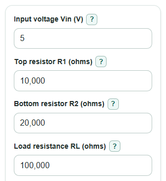
For Input voltage Vin (V) = 5, Top resistor R1 (ohms) = 10,000, Bottom resistor R2 (ohms) = 20,000, and Load resistance RL (ohms) = 100,000, the no-load output is 3.333 V. R2 in parallel with RL is 16,666.7 ohms, so the loaded output is 3.125 V. The signed output change is -6.25 percent. The Thevenin resistance is 6,666.7 ohms, so a 5 percent allowed change needs a minimum load of 126,666.7 ohms. A 100,000 ohm load does not pass that 5 percent limit.