
Find the RV solar wire size that keeps voltage drop within your target, or check a wire you already have.
Table of contents
How to use our RV Solar Wire Size Calculator
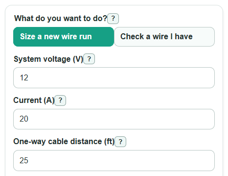
- Choose What do you want to do?: Size a new wire run for a recommendation, or Check a wire I have to test an Existing wire size (AWG).
- Enter System voltage (V), Current (A), One-way cable distance (ft), and Max voltage drop (percent). Measure the cable route one way only; the calculator counts the return wire for you.
- Use Advanced options only when needed: set RV solar wire location for the note, choose Wire material, add Extra current cushion (percent), or set Matching wire sets in parallel.
- Click Calculate, then read Main answer first. Use Voltage lost in the wire, Voltage lost in the wire percent, Voltage at the far end, and Power lost as heat to judge the tradeoff.
- Sanity-check the result: a 12 V system with high Current (A) or a long One-way cable distance (ft) usually needs much thicker wire than a 24 V or 48 V system carrying the same watts.
Definitions
AWG: American Wire Gauge, a common wire size scale where smaller gauge numbers mean thicker wire.
Circular mils: A wire area unit used in AWG tables. More circular mils means a larger conductor.
System voltage (V): The working DC voltage for the wire section you are sizing, such as 12 V battery wiring or a higher-voltage solar array run.
Current (A): The steady current in amps that the wire carries for the voltage drop check.
One-way cable distance (ft): The measured route length from power source to device in one direction. A DC circuit uses both a positive and negative path.
Voltage drop: Voltage lost because the wire has resistance. Lower voltage drop means more voltage reaches the device.
Full-circuit wire resistance: The resistance of the complete out-and-back wire path used in the voltage drop math.
Power lost as heat: Watts turned into heat in the cable instead of reaching the load or charge controller.
Matching wire sets in parallel: Two or more equal wire pairs sharing the same current path. They must be matched in size and length to share current well.
Common mistakes and quick fixes
Mistake: Entering the full round-trip cable length in One-way cable distance (ft).
Fix: Enter the distance from the source to the device one way; the calculator doubles it for Full-circuit wire resistance.
Mistake: Using panel open-circuit voltage for System voltage (V) on a loaded solar run.
Fix: Use the working DC voltage for the wire section, such as panel operating voltage into a controller or battery voltage from controller to battery.
Mistake: Leaving Max voltage drop (percent) blank or typing 0.
Fix: Enter a positive target such as 3 if you want the wire checked against a 3 percent voltage drop limit.
Mistake: Forgetting that Extra current cushion (percent) changes Current used for sizing.
Fix: Leave Extra current cushion (percent) at 0 if Current (A) already includes your safety margin.
Mistake: Selecting Copper in Wire material when the installed cable is aluminum.
Fix: Match Wire material to the actual conductor, and verify terminals are rated for that material.
Mistake: Choosing 2 or more Matching wire sets in parallel when the wires will not be the same size and length.
Fix: Use 1 set unless each parallel positive and negative path is matched so current can share evenly.
Limitations & Key Assumptions / Boundary Conditions
- This calculator estimates DC voltage drop only. It does not choose fuse size, breaker size, ampacity, insulation temperature rating, connector rating, or code-compliant installation details.
- The recommendation scans common AWG sizes from 18 AWG through 4/0 AWG. If none pass, the result is an unsupported state instead of a custom cable size.
- Resistance is estimated at about 20 C using copper or aluminum constants. Hot cable, tightly bundled cable, poor crimps, corroded terminals, and real strand construction can change the actual voltage drop.
- For panel-to-controller wiring, System voltage (V) should be the operating voltage under load, not the open-circuit voltage printed as Voc.
- Parallel wire sets assume matching positive wires and matching negative wires with equal length, equal gauge, and good connections. Unequal paths may not share current evenly.
- Voltage at the far end is not clamped to zero. A negative value means the entered current, length, and wire resistance are not a practical setup.
- Aluminum results are math estimates only. Many RV solar devices and lugs are rated for copper only, so verify termination ratings before using aluminum cable.
Methodology
What the calculator solves
The calculator uses DC voltage drop math for a complete positive-and-negative circuit. In size mode, it tests the listed AWG sizes from thin to thick and returns the first size that keeps voltage drop at or below your Max voltage drop (percent). In check mode, it calculates the drop for Existing wire size (AWG) and separately finds the smallest listed size that would pass.
Constants and lookup values
Common AWG circular mil areas are taken from standard AWG table values, including 10 AWG = 10,380 circular mils, 8 AWG = 16,510 circular mils, 4 AWG = 41,740 circular mils, and 4/0 AWG = 211,600 circular mils [1]. The resistance constants used are 10.371 ohm-cmil/ft for copper and 16.946 ohm-cmil/ft for aluminum. A thicker wire has less resistance, so long low-voltage runs often need a larger conductor to control voltage drop [1].
Formulas used
adjusted_current_a = current_a * (1 + current_cushion_percent / 100)
wire_resistance_ohms = k_material_ohm_cmil_per_ft * (2 * one_way_length_ft) / (cmil * parallel_sets)
voltage_drop_volts = adjusted_current_a * wire_resistance_ohms
voltage_drop_percent = (voltage_drop_volts / system_voltage_v) * 100
passes_target_flag = 1 if voltage_drop_percent <= max_drop_percent else 0
voltage_at_end_v = system_voltage_v - voltage_drop_volts
power_lost_w = adjusted_current_a * voltage_drop_volts
area_mm2 = cmil * 0.000506707479
The factor 2 in the resistance formula counts the positive and negative conductors in a DC circuit. The pass or fail comparison allows a tiny floating-point tolerance so a result exactly on the target does not flicker between pass and fail.
Mini-example
Suppose System voltage (V) is 12, Current (A) is 20, One-way cable distance (ft) is 25, Max voltage drop (percent) is 3, Wire material is Copper, Extra current cushion (percent) is 0, and Matching wire sets in parallel is 1. The adjusted current is 20 A. For 4 AWG copper, the full-circuit resistance is about 0.012423 ohms. The voltage drop is about 0.248 V, which is about 2.07 percent of 12 V. Voltage at the far end is about 11.75 V, and Power lost as heat is about 4.97 W, so 4 AWG passes the 3 percent target.
How to read the result
Main answer is the practical recommendation or pass/fail message. Meets your voltage drop target tells whether the calculated percent drop is at or below your target. Voltage lost in the wire and Power lost as heat show the cost of cable resistance. Voltage drop is separate from ampacity, and solar wire should not be sized only by ampacity in low-voltage circuits [3].