
Calculate the nearest two-tone IM3 product frequencies and powers, or find IIP3 or OIP3 from measured spectrum-analyzer levels.
Tone setup
Level data
Advanced options
Frequency display
| IM3 product | Frequency | Power | Below its tone |
|---|---|---|---|
| 2F1-F2 | |||
| 2F2-F1 |
Table of contents
How to use our RF Intermodulation Products and Third-Order Intercept Calculator
- Choose what you want to calculate, making sure the mode matches the reference plane of your power values: input for IIP3 or output for OIP3.
- Choose the Tone frequency unit, then enter Low tone F1 frequency and High tone F2 frequency as shown on your generator, analyzer, or channel plan.
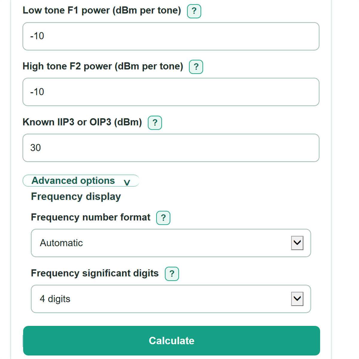
- Enter Low tone F1 power and High tone F2 power as separate absolute dBm values per tone.
- For a prediction, enter Known IIP3 or OIP3. For a measured-data mode, enter the absolute dBm analyzer markers for Measured 2F1-F2 power and Measured 2F2-F1 power.
- Check that each result row matches the expected analyzer marker frequency and that both intercept estimates are reasonably close before relying on their average.
Definitions
F1 and F2: The low and high test-tone frequencies. This calculator requires F2 to be greater than F1.
IM3: A third-order intermodulation product made by two tones. The nearest products are 2F1-F2 and 2F2-F1.
dBm: Absolute power referenced to 1 milliwatt. A negative dBm value is valid and means power below 1 milliwatt.
dBc: Power relative to a carrier or tone, measured in decibels. A positive suppression value means the IM3 product is that many dB below its associated tone.
IIP3: Input third-order intercept point, referenced to the device input plane.
OIP3: Output third-order intercept point, referenced to the device output plane.
Third-order intercept: An extrapolated point where the fundamental and third-order response lines would meet; it is used to compare third-order linearity. [1]
Common mistakes and quick fixes
Mistake: Entering total two-tone power in Low tone F1 power or High tone F2 power.
Fix: Enter the power of each individual tone in dBm per tone.
Mistake: Entering a GHz number while Tone frequency unit is set to MHz.
Fix: Set Tone frequency unit first, then enter both frequency values in that unit.
Mistake: Putting the higher frequency into Low tone F1 frequency.
Fix: Put the smaller positive frequency in Low tone F1 frequency and the larger one in High tone F2 frequency.
Mistake: Typing a relative reading such as 58 dBc into Measured 2F1-F2 power.
Fix: Enter the analyzer marker's absolute power in dBm; the calculator finds suppression in dBc separately.
Mistake: Mixing input-plane levels with Known IIP3 or OIP3 from an output-plane data sheet value.
Fix: Use IIP3 only with input-plane values and OIP3 only with output-plane values in the selected mode.
Limitations & Key Assumptions / Boundary Conditions
- The calculation uses a two-tone third-order model. It predicts only the nearest products, 2F1-F2 and 2F2-F1, not second-order products, harmonics, or products from many carriers.
- All entered dBm values must use one consistent reference plane. The calculator does not convert between IIP3 and OIP3 because it does not ask for gain.
- IP3 is an extrapolated linearity metric. A predicted product near or above its associated tone is outside normal small-distortion conditions and may not describe actual device behavior.
- Measured low-side and high-side products can differ because of device asymmetry, test setup, analyzer uncertainty, filters, compression, or noise. The calculated intercept is their average, while both side estimates remain visible.
- Frequency formatting and significant digits change only the displayed product frequency, not the calculation.
Methodology
Frequency calculation
The calculator converts both entered tone frequencies to Hz, calculates each IM3 frequency, then converts the answers back to the selected unit. F2 must be greater than F1, and the low-side product must be above 0 Hz.
im3_low_hz = 2 * f1_hz - f2_hz
im3_high_hz = 2 * f2_hz - f1_hz
Predicting IM3 power
In either prediction mode, the entered intercept and both per-tone powers must be referenced to the selected input or output plane. Unequal tone powers are kept separate. These equations follow the usual two-tone third-order relationship. [1]
im3_low_level_dbm = 2 * tone1_power_dbm + tone2_power_dbm - 2 * intercept_dbm
im3_high_level_dbm = 2 * tone2_power_dbm + tone1_power_dbm - 2 * intercept_dbm
Calculating intercept from measured products
In a measured-data mode, each analyzer marker produces its own intercept estimate. The displayed IIP3 or OIP3 is the average of those two estimates, so a mismatch is not hidden. [2]
intercept_low_dbm = (2 * tone1_power_dbm + tone2_power_dbm - measured_im3_low_dbm) / 2
intercept_high_dbm = (2 * tone2_power_dbm + tone1_power_dbm - measured_im3_high_dbm) / 2
third_order_intercept_dbm = (intercept_low_dbm + intercept_high_dbm) / 2
Suppression and example
Suppression compares each absolute IM3 power with its matching fundamental tone.
im3_low_suppression_dbc = tone1_power_dbm - im3_low_level_dbm
im3_high_suppression_dbc = tone2_power_dbm - im3_high_level_dbm
For F1 = 900 MHz, F2 = 901 MHz, F1 power = -10 dBm, F2 power = -12 dBm, and OIP3 = 30 dBm, the low-side product is 899 MHz at -92 dBm and the high-side product is 902 MHz at -94 dBm. Each is 82 dBc below its associated tone.
Assumptions and limits
The method assumes absolute dBm measurements at one reference plane and a third-order response suitable for extrapolation. It does not account for gain, compression, frequency-dependent behavior, filters, analyzer settings, or multiple-carrier effects.