
Enter two known values to find the ideal cutoff frequency, resistor, or capacitor for an RC low-pass filter with output across the capacitor.
Advanced options
This is a component-tolerance corner estimate, not a guaranteed measured limit.
This range uses the smallest allowed resistance and capacitance.
One time constant describes the ideal charging or discharging time scale.
A negative value means the output amplitude is lower than the input amplitude.
A negative angle means the output lags the input.
Table of contents
How to use our RC Low Pass Filter Calculator
- Choose what you want to find from "Find": cutoff frequency, resistance, or capacitance.
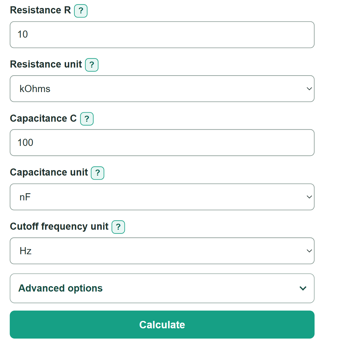
- Enter the other two known values, then choose the units printed on the component, schematic, or design requirement.
- Click "Calculate" to see the requested ideal value first, followed by the RC time constant.
- Sanity-check the result: increasing either resistance or capacitance should lower the cutoff frequency.
- Open "Advanced options" to check a signal frequency or enter both part tolerances for a possible cutoff range.
Definitions
RC low-pass filter: A series resistor and a capacitor connected to ground, with output measured across the capacitor. It reduces higher frequencies more than lower frequencies.
Cutoff frequency (fc): The ideal frequency where output amplitude is about 0.707 times input amplitude, equal to -3 dB. [1]
Resistance (R): Opposition to electric current, measured in ohms. One kOhm is 1,000 ohms, and one MOhm is 1,000,000 ohms.
Capacitance (C): A capacitor's ability to store electric charge, measured in farads. Common units include pF, nF, and uF.
Time constant (RC or tau): Resistance multiplied by capacitance, measured in seconds. It sets the ideal charging and discharging time scale. [2]
Gain (dB): Output amplitude compared with input amplitude on a logarithmic scale. A negative gain means the signal is reduced.
Phase: The timing angle between output and input. Negative phase means the capacitor output lags the input.
Common mistakes and quick fixes
Mistake: Measuring output across the resistor.
Fix: This is a low-pass model only when output is measured across the capacitor. Output across the resistor makes a high-pass circuit.
Mistake: Entering a capacitor value with the wrong unit.
Fix: For 100 nF, choose nF and enter 100, or enter a supported suffix such as 100n.
Mistake: Treating cutoff as a sharp boundary.
Fix: Cutoff is the ideal -3 dB point. Higher frequencies are reduced gradually instead of being completely removed.
Mistake: Entering only one part tolerance.
Fix: Enter both "Resistor tolerance (%)" and "Capacitor tolerance (%)", or clear both fields. The range needs both values.
Mistake: Entering a tolerance of 100%.
Fix: Enter each tolerance from 0% to less than 100%. A 100% tolerance permits a zero-value part in this model.
Mistake: Expecting an ideal answer to match every real circuit.
Fix: Account for source resistance, load resistance, capacitor ESR, wiring, and measurement equipment when testing the built circuit.
Limitations & Key Assumptions / Boundary Conditions
- This calculator models an ideal first-order passive circuit with a series resistor, capacitor to ground, and output across the capacitor.
- Active resistance, capacitance, and cutoff frequency values must be greater than zero.
- The tolerance range uses independent, symmetric plus-or-minus resistor and capacitor tolerances. It is a corner estimate, not a guaranteed measured range.
- The signal check applies to a steady-state sine wave and does not model startup charging, switching, or non-sine signals.
- Source resistance, load resistance, capacitor ESR, capacitor ESL, leakage, parasitic capacitance, temperature, and measurement equipment can shift the real response.
- At sufficiently high frequencies, component layout and wiring can make the first-order model inaccurate.
Methodology
Ideal RC calculation
The calculator converts entered values to ohms, farads, and hertz. For a first-order low-pass circuit with output across the capacitor, it uses the standard cutoff relationship. [1]
fc = 1 / (2 * pi * R * C)
R is resistance in ohms, C is capacitance in farads, and fc is cutoff frequency in hertz. To find a missing part value, the calculator rearranges the same equation.
R = 1 / (2 * pi * fc * C)
C = 1 / (2 * pi * fc * R)
The time constant uses the final resistor and capacitor values.
tau = R * C
Optional checks
When both component tolerances are entered, the lowest cutoff uses the largest permitted resistance and capacitance. The highest cutoff uses the smallest permitted values.
fc_low = fc / ((1 + Rtol/100) * (1 + Ctol/100))
fc_high = fc / ((1 - Rtol/100) * (1 - Ctol/100))
For an optional signal frequency f, the calculator estimates the ideal capacitor-output amplitude ratio, gain, and phase.
amplitude ratio = 1 / sqrt(1 + (f/fc)^2)
gain dB = 20 * log10(amplitude ratio)
phase degrees = -atan(f/fc) * 180 / pi
Worked mini-example
With R = 10 kOhms and C = 100 nF, tau = 0.001 s and the ideal cutoff is about 159.15 Hz. At 1 kHz, the ideal amplitude ratio is about 0.157, the gain is about -16.07 dB, and the output phase is about -80.96 degrees.
Calculation conditions
These equations assume ideal parts, negligible source and load effects, and steady-state sine-wave behavior. A built circuit can differ when connected to other parts or when parasitic effects become important.