
Find an RC high-pass filter cutoff frequency, missing resistor, or missing capacitor, then check one real signal frequency.
Advanced options
Table of contents
How to use our RC High Pass Filter Calculator
- Choose what to find in What do you want to find?; the calculator hides the value it will solve.
- Enter the visible part values, such as Resistor value (ohms), Capacitor value (uF), or Cutoff frequency (Hz).
- Enter Signal frequency to check (Hz) to see how much of that signal reaches the output.
- Use Advanced options only when your source or next circuit stage matters; add Input signal size (V) if you want an estimated output voltage.
- Sanity-check the result: at the cutoff frequency, an ideal unloaded high-pass filter should keep about 0.707 V/V and show about -3.01 dB.
Definitions
High-pass filter: A circuit that lets faster signal changes pass better than slow changes or DC.
Cutoff frequency: The frequency where this first-order filter is down to 1/sqrt(2), about 0.707 V/V, compared with its high-frequency passband.
Resistor value (ohms): The filter resistor across which the output voltage is taken in the basic RC high-pass circuit.
Capacitor value (uF): The capacitance entered in microfarads; 1 uF equals 0.000001 farads.
Signal kept at the check frequency: The voltage gain ratio Vout/Vin at the signal frequency you entered.
Gain at the check frequency: The same gain written in decibels, where negative dB means the output is smaller than the input.
Capacitor reactance: The capacitor's AC opposition at a frequency; it gets smaller as frequency gets higher [3].
RC time constant: The resistance path multiplied by capacitance, in seconds.
Common mistakes and quick fixes
Mistake: Entering nanofarads in Capacitor value (uF) without converting.
Fix: Convert first; for example, 100 nF is 0.1 uF.
Mistake: Using a zero or negative Signal frequency to check (Hz) .
Fix: Enter a signal frequency greater than 0 Hz.
Mistake: Leaving Cutoff frequency (Hz) at an old value when What do you want to find? is set to find a resistor or capacitor.
Fix: Type the cutoff frequency you actually want before you calculate.
Mistake: Ignoring Source resistance (ohms) when the signal source has real output resistance.
Fix: Enter the source resistance, or leave it at 0 only for an ideal source.
Mistake: Entering the load as part of Resistor value (ohms) instead of using Load resistance (ohms) .
Fix: Put the filter resistor in Resistor value (ohms) and the next stage input resistance in Load resistance (ohms) .
Mistake: Mixing voltage styles in Input signal size (V) and Estimated output signal size .
Fix: Use the same style, such as RMS, peak, or peak-to-peak, for both reading and interpretation.
Limitations & Key Assumptions / Boundary Conditions
- This calculator models a first-order passive RC high-pass filter with the output taken across the resistor.
- Advanced loading uses source resistance in series and load resistance in parallel with the filter resistor; real circuits with active parts, coupling networks, or non-resistive loads can behave differently.
- Capacitor tolerance, resistor tolerance, temperature, and breadboard stray capacitance are not included.
- The gain and phase are small-signal sine-wave results. Large signals, clipping, and nonlinear parts are outside this model.
- When solving for a resistor with a load, some requested cutoff values are impossible with a positive filter resistor; the calculator treats those as errors.
- Input signal size (V) can be RMS, peak, or peak-to-peak, but the calculator does not convert between those styles.
Methodology
Core calculation
The calculator first converts capacitance from microfarads to farads, then builds the resistance seen by the capacitor. If Load resistance (ohms) is blank, the parallel resistance is just the filter resistor. If a load is entered, it is placed in parallel with the filter resistor.
C_F = C_uF * 1e-6
R_parallel = 1 / (1/R + 1/R_load)
R_path = R_source + R_parallel
fc = 1 / (2 * pi * R_path * C_F)
Solving for a missing part
When you choose Find resistor value, the calculator finds the needed resistance path, subtracts source resistance, then converts the needed parallel resistance back into the actual filter resistor if a load is present.
target_path = 1 / (2 * pi * fc * C_F)
target_parallel = target_path - R_source
R = target_parallel
R = (target_parallel * R_load) / (R_load - target_parallel)
When you choose Find capacitor value, the calculator uses the resistance path and desired cutoff frequency to find capacitance.
C_F = 1 / (2 * pi * fc * R_path)
C_uF = C_F / 1e-6
Signal check at one frequency
For Signal frequency to check (Hz), the calculator finds capacitor reactance, voltage gain, gain in decibels, and phase lead. If Input signal size (V) is entered, it multiplies that input by the gain.
Xc = 1 / (2 * pi * f_test * C_F)
gain = R_parallel / sqrt(R_path^2 + Xc^2)
gain_dB = 20 * log10(gain)
phase_degrees = atan(Xc / R_path) * 180 / pi
output_signal_v = input_signal_v * gain
Worked mini-example
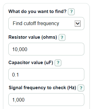
With Resistor value (ohms) = 10000, Capacitor value (uF) = 0.1, no source resistance, no load, and Signal frequency to check (Hz) = 1000, the capacitance is 0.0000001 F and the RC time constant is 0.001 s. The cutoff frequency is 1 / (2 * pi * 0.001), or about 159.15 Hz. At 1000 Hz, the reactance is about 1591.55 ohms and the signal kept is about 0.9876 V/V, so most of that 1000 Hz signal passes.