
Calculate water pipe pressure loss, allowed flow, or required inside diameter for a Schedule 40 PVC run.
Advanced options
Pipe run adjustments
Result display
Calculation details
Table of contents
How to use our Pipe Flow Rate, Diameter and Pressure Loss Calculator
- Choose what you want to find: pressure loss, flow rate, or inside diameter.
- Enter the water temperature and straight pipe length. Use the length of straight pipe only.
- For a pressure-loss check, enter Water flow rate and choose the Schedule 40 PVC pipe size. For the other modes, enter the visible required values instead.
- Open Advanced options only if you need to add Fittings and valves total K, elevation change, or a known Pipe roughness.
- Click Calculate, then check Water speed in the pipe and Pressure needed across the run. A higher outlet elevation should increase the pressure needed, while a lower outlet elevation can reduce it.
Definitions
Actual inside diameter: The open width inside the pipe. It is the diameter used for flow calculations and can differ from the nominal pipe label.
Nominal pipe size: A trade label printed on pipe or used in catalogs. It is not necessarily the measured inside diameter.
Fittings and valves total K: A unitless number that adds pressure loss from elbows, tees, valves, and similar parts.
Friction pressure loss: Pressure used to push water through straight pipe and entered fittings.
Reynolds number: A unitless value used to identify laminar, transition, or turbulent flow and select the friction-factor method.
Darcy friction factor: A unitless number used in the Darcy-Weisbach equation to calculate pipe friction loss.
Friction head loss: Friction loss expressed as feet of water rather than psi.
Common mistakes and quick fixes
Mistake: Using the nominal label as the inside diameter, such as treating 1 in pipe as a 1.000 in opening.
Fix: Choose Schedule 40 PVC pipe size and use Selected pipe actual inside diameter shown in the result.
Mistake: Including elbows and valves in Straight pipe length and also entering Fittings and valves total K.
Fix: Enter straight length only, then add fitting losses once with Fittings and valves total K.
Mistake: Entering a negative value for Fittings and valves total K.
Fix: Enter 0 or a positive K value; fittings and valves add friction loss.
Mistake: Reversing Outlet elevation minus inlet elevation (ft).
Fix: Use a positive number when the outlet is higher and a negative number when the outlet is lower.
Mistake: Treating Friction pressure loss as the full Pressure needed across the run.
Fix: Use Pressure needed across the run when elevation is included; Friction pressure loss excludes elevation pressure.
Mistake: Entering a water temperature outside the supported range.
Fix: Enter Water temperature from 40 to 120 deg F, or use a different engineering method for conditions outside that range.
Limitations & Key Assumptions / Boundary Conditions
- This calculator models single-phase, incompressible liquid water in one round Schedule 40 PVC pipe run. Do not use it for air, other gases, steam, boiling water, flashing, or two-phase flow.
- Water density and viscosity are interpolated only from 40 to 120 deg F. Values outside that range are blocked rather than extrapolated.
- The default smooth-wall estimate uses Pipe roughness of 0. Enter a supported project roughness when wall condition is known.
- Friction pressure loss includes fittings only when Fittings and valves total K is entered. It includes elevation only when Outlet elevation minus inlet elevation (ft) is entered.
- The pipe recommendation is limited to the loaded Schedule 40 PVC sizes from 1/2 in through 2 in nominal. A required inside diameter above that range has no matching loaded option.
- Results estimate steady flow. Pump behavior, changing demand, entrance and exit losses, local code, pipe damage, and downstream equipment requirements can change a real installation.
Methodology
Calculation method
The calculator uses Darcy-Weisbach pipe-friction analysis. It converts the selected Schedule 40 PVC nominal label to its actual inside diameter, converts GPM to cubic feet per second, and finds average water speed from flow divided by pipe area. Water density and dynamic viscosity are linearly interpolated from the loaded 40 to 120 deg F water table. [1]
A = πD2 / 4
v = Q / A
In these equations, A is inside area, D is actual inside diameter, v is water speed, and Q is flow rate.
Re = ρvD / μ
The Reynolds number, Re, uses water density ρ and dynamic viscosity μ. For Reynolds numbers below 2300, the Darcy friction factor is 64 / Re. At 2300 and above, the calculator uses the explicit Haaland turbulent-flow approximation with relative roughness.
ΔP = (fL / D + K) x (ρv2 / 2)
This pressure-loss equation combines the Darcy friction factor f, straight pipe length L, actual diameter D, and entered fittings total K. The dynamic-pressure part is converted to psi. Elevation is calculated separately from water density and signed elevation change, then added to friction pressure loss to produce Pressure needed across the run.
Prequired = Pfriction + Pelevation
Solving for flow or diameter
When you choose Flow rate or Inside diameter, the calculator repeatedly tests nonnegative flow values or positive inside diameters until the complete pressure requirement matches Pressure available for this run. It does not treat the nominal pipe label as an actual diameter.
Worked example
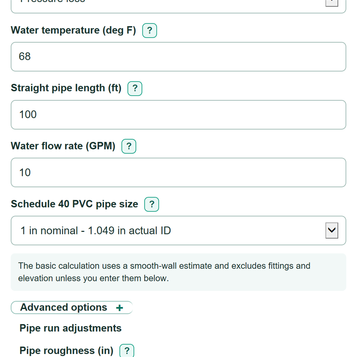
With water at 68 deg F, 100 ft of 1 in nominal Schedule 40 PVC, and 10 GPM, the selected actual inside diameter is 1.049 in. With no entered fittings or elevation change, the modeled Friction pressure loss is about 2.469 psi, water speed is about 3.712 ft/s, and Friction head loss is about 5.705 ft of water. If 10 ft of uphill elevation is added, the friction result stays the same but Pressure needed across the run increases because lifting water needs additional pressure.
Calculation choices
Pressure loss per 100 ft reports distributed straight-pipe friction only, so it excludes fittings and elevation. The displayed Flow pattern uses laminar below 2300, transition from 2300 to below 4000, and turbulent at 4000 or higher. Values are calculated before display rounding.