
Enter the value and unit for each capacitor across the same two nodes to find the group's equivalent capacitance.
This ideal total applies when every entered capacitor connects across the same two nodes.
Table of contents
How to use our Parallel Capacitor Calculator
- Check the schematic or wiring: every capacitor you include must connect across the same two circuit nodes.
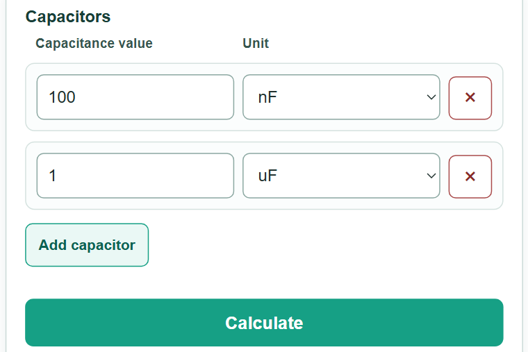
- Enter each capacitor's capacitance value and choose its marked unit, such as pF, nF, or uF.
- Select "Add capacitor" for each additional part in the same parallel group, then select "Calculate".
- Check the added-capacitances line against your schematic or parts list. The total should include every entered part and should never be smaller than any individual positive capacitance.
Definitions
Capacitance: A part's ability to store electric charge at a given voltage difference. It is measured in farads.
Farad (F): The base SI unit of capacitance.
pF, nF, uF, and mF: Picofarad, nanofarad, microfarad, and millifarad. One uF is 1,000 nF and 1,000,000 pF.
Parallel capacitors: Capacitors with both terminals connected across the same two circuit nodes. Their capacitances add directly. [1]
Equivalent capacitance: One ideal capacitance with the same total capacitance as the entered parallel group.
Common mistakes and quick fixes
Mistake: Using the reciprocal rule for capacitors in series.
Fix: Use this calculator only for a true parallel group. Parallel capacitances add after their units are converted.
Mistake: Adding 100 nF and 1 uF as 101 of the same unit.
Fix: Keep each row's actual unit. The calculator converts all rows to farads before adding.
Mistake: Including parts that do not connect across the same two nodes.
Fix: Trace both terminals on the schematic or wiring. Leave out capacitors in a series or mixed network.
Mistake: Entering a voltage rating, such as 25 V, instead of capacitance.
Fix: Enter the capacitance marking, such as 10 uF. Voltage rating is a separate part specification.
Mistake: Treating the marked total as exact real-circuit behavior.
Fix: Use the result as a nominal ideal total, then check tolerance, DC bias, temperature, and relevant part specifications.
Limitations & Key Assumptions / Boundary Conditions
- The result applies only when every entered capacitor is connected across the same two circuit nodes.
- The result is a nominal ideal capacitance total. It does not calculate tolerance, temperature effects, DC bias, aging, leakage, ESR, ESL, ripple-current capability, or dielectric behavior.
- Do not use this addition rule for series networks or mixed series-parallel networks.
- Voltage ratings do not add in parallel. Each real capacitor must still be suitable for the circuit voltage and operating conditions.
- Very small or very large nonzero totals may use scientific notation so they are not displayed as zero.
Methodology
Calculation method
Each entered capacitance is converted to farads, then the converted values are added. For capacitors in parallel, capacitance adds directly. [1]
C_eq = C_1 + C_2 +... + C_n
C_eq means equivalent capacitance. Each C value is one entered capacitor after all values use the same unit. The calculator converts between F, mF, uF, nF, and pF using exact metric prefixes, then chooses a readable unit for the main answer.
Worked example
With 100 nF and 1 uF in parallel, 100 nF equals 0.1 uF. Adding 0.1 uF and 1 uF gives 1.1 uF, which is 0.0000011 F.
100 nF + 1 uF = 0.1 uF + 1 uF = 1.1 uF
Input handling
At least two complete rows are required. Zero is allowed and adds zero to the total. Negative, nonfinite, incomplete, and unsupported entries are rejected rather than included in the calculation.