
Calculate baghouse air-to-cloth ratio, filter area, total pressure, fan shaft load, and electrical input from ACFM and field data.
Airflow and filter area
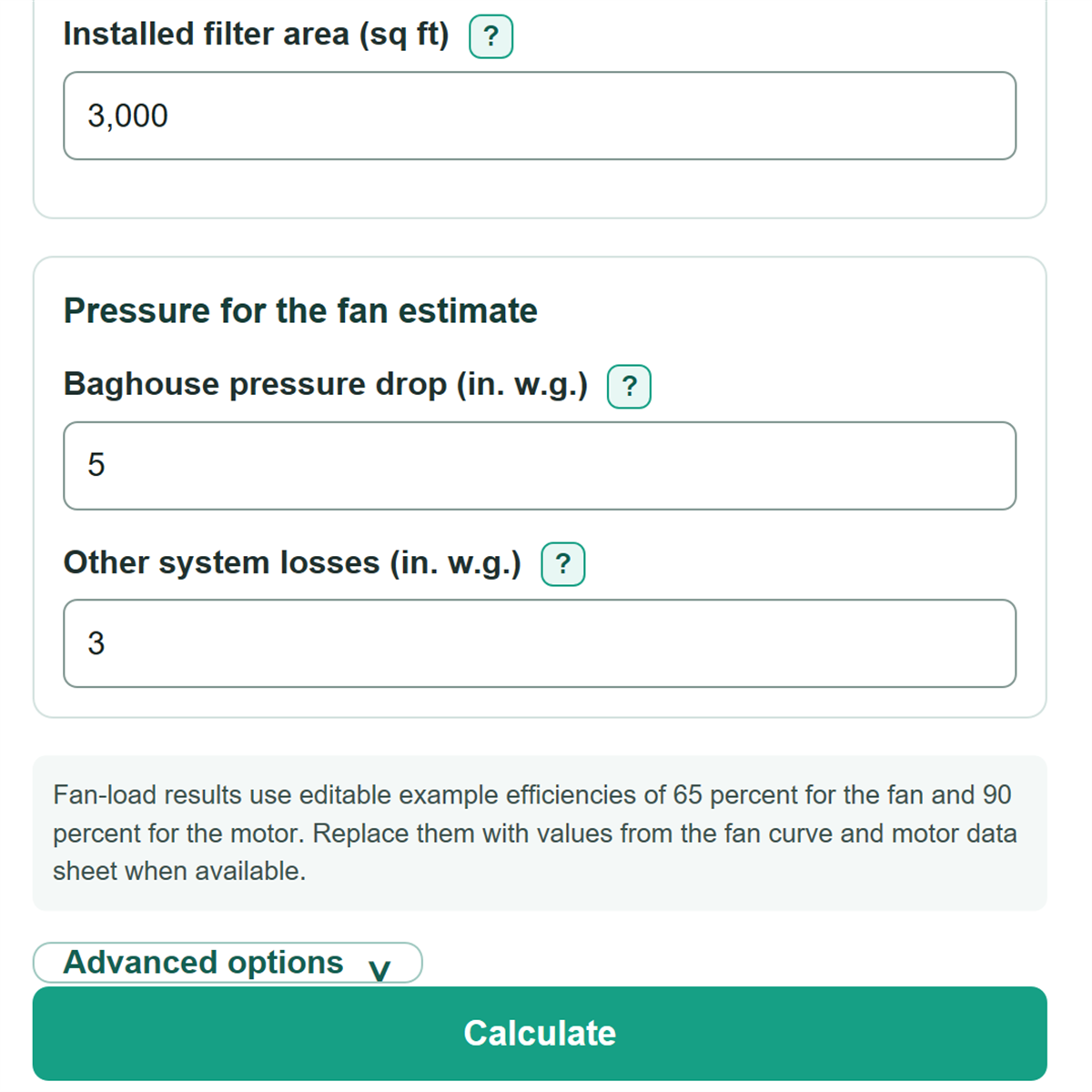
Pressure for the fan estimate
Advanced options
This is airflow divided by installed filter area. Compare it with an OEM or project target, not a universal pass or fail limit.
This is a preliminary cloth-area requirement. Final selection depends on the dust, media, cleaning method, moisture, temperature, and collector layout.
Estimated power delivered at the fan shaft. This is not a motor nameplate recommendation.
Estimated input at this operating point. It is not annual energy use.
Baghouse pressure drop plus the other entered system losses.
Geometry mode uses the filtering side surface of each cylindrical bag and excludes the bag ends.
Power transferred to the air before fan and motor losses.
Table of contents
How to use our Baghouse Air-to-Cloth Ratio, Filter Area and Fan Load Calculator
- Choose the option under "What do you want to calculate?" that matches your job: a known area check, bag dimensions, or proposed collector sizing.
- Enter "Airflow at the collector (ACFM)" from an airflow test, fan curve operating point, or plant display. Use actual airflow, not SCFM.
- Enter the visible area inputs for your selected path, then enter "Baghouse pressure drop (in. w.g.)" and "Other system losses (in. w.g.)."
- Open Advanced options to replace the example "Fan total efficiency (percent)" and "Motor efficiency (percent)" with values from equipment data.
- Click Calculate, then sanity-check that "Total pressure used for fan load" equals the two pressure entries added together and compare the air-to-cloth ratio with your project or OEM target.
Definitions
ACFM: Actual cubic feet per minute, meaning airflow at the collector's real temperature and pressure.
Air-to-cloth ratio: Airflow divided by filter cloth area. It is shown as ft/min and as x:1.
Installed filter area: Total filter cloth area used in the check, either entered directly or calculated from bag dimensions.
Active bag length: The portion of a filter bag that is exposed to airflow and filters dust.
In. w.g.: Inches of water gauge, a pressure unit commonly used for baghouse and duct losses.
Fan total efficiency: The share of input shaft power that becomes useful air power at the stated fan operating point.
Motor efficiency: The share of electrical input converted into mechanical power at the motor shaft.
Common mistakes and quick fixes
Mistake: Entering SCFM in "Airflow at the collector (ACFM)".
Fix: Convert standard airflow to actual collector conditions before entry, or use a measured actual airflow value.
Mistake: Treating "Installed filter area (sq ft)" as interchangeable with every vendor area figure.
Fix: Use one consistent gross, net, nominal, or effective area basis when checking "Actual air-to-cloth ratio."
Mistake: Including bag hardware or a non-filtering section in "Active bag length (feet)."
Fix: Enter only the cloth length exposed to filtration.
Mistake: Entering only collector differential pressure in "Baghouse pressure drop (in. w.g.)" and leaving out duct losses.
Fix: Put applicable hood, duct, fitting, damper, inlet, and outlet losses in "Other system losses (in. w.g.)."
Mistake: Reading "Estimated fan shaft load" as the motor nameplate size.
Fix: Treat it as an operating-point estimate; motor selection also needs starting, service, drive, and application requirements.
Limitations & Key Assumptions / Boundary Conditions
- This is a preliminary steady operating-point calculation, not a complete baghouse or fan selection.
- Use ACFM at the collector. SCFM, CFM at another location, or an airflow value from a different operating condition can change every airflow-based result.
- The calculated bag area treats each bag as an open-ended cylinder using its active cloth length. It does not model pleats, seams, ends, cages, damaged bags, or non-filtering sections.
- Air-to-cloth ratio is not a universal pass or fail value. Dust type, loading, moisture, temperature, media, cleaning method, and collector design can require a different target.
- The fan estimate uses the entered baghouse pressure drop plus other system losses. It does not include unentered losses, changing filter cake pressure, drive losses, electrical distribution losses, controls, or compressed-air cleaning.
- Fan and motor efficiencies must match the actual operating point as closely as possible. The editable example values are not equipment ratings or design recommendations.
- Estimated electrical input is instantaneous kW, not annual kWh, utility cost, demand charge, or motor nameplate size.
Methodology
Calculation method
The selected path supplies the filter area. Known-area mode uses the entered installed area. Bag-dimension mode calculates the side area of cylindrical bags. Proposed-size mode calculates the area needed for the entered target ratio.
Area (sq ft) = bag count x π x [bag diameter (inches) / 12] x active bag length (feet)
Actual air-to-cloth ratio (ft/min) = airflow (ACFM) / installed filter area (sq ft)
Required filter area (sq ft) = airflow (ACFM) / target air-to-cloth ratio (ft/min)
The fan calculation adds collector pressure and external losses first. It then calculates theoretical air power, divides by fan total efficiency for shaft load, and divides by motor efficiency for electrical input.
Total pressure (in. w.g.) = baghouse pressure drop + other system losses
Theoretical air power (hp) = airflow (ACFM) x total pressure (in. w.g.) / 6356
Fan shaft load (hp) = theoretical air power / [fan total efficiency / 100]
Electrical input (kW) = fan shaft load (hp) x 0.745699872 / [motor efficiency / 100]
Worked example
With 12,000 ACFM and 3,000 sq ft of installed area, the actual air-to-cloth ratio is 4 ft/min, or 4:1. With 5 in. w.g. of baghouse pressure drop, 3 in. w.g. of other losses, 65 percent fan total efficiency, and 90 percent motor efficiency, total pressure is 8 in. w.g., estimated fan shaft load is 23.24 hp, and estimated electrical input is 19.25 kW.