
Estimate rectifier DC voltage, ripple, peak voltage, and diode voltage rating from an AC RMS input.
Advanced options
Table of contents
How to use our AC to DC Rectifier Voltage Calculator
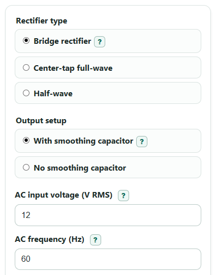
- Choose the Rectifier type that matches your circuit: Bridge rectifier, Center-tap full-wave, or Half-wave.
- Choose Output setup based on the real circuit. Pick With smoothing capacitor only if a capacitor is connected across the rectifier output.
- Enter AC input voltage (V RMS), AC frequency (Hz), and Drop per diode (V). For center-tap transformers, enter the RMS voltage from one end of the winding to the center tap.
- If Output setup is With smoothing capacitor, enter Load current (A) and Filter capacitor (uF). Open Advanced options only if you want tolerance checks, a PIV safety factor, or a different Number display.
- Click Calculate, then sanity-check the result: Estimated DC output should be below Peak after diode drops, and Lowest estimated capacitor voltage should not be far below the voltage your circuit needs.
Definitions
AC input voltage (V RMS): The RMS voltage of the AC source. RMS is the AC value that gives the same heating power as that many volts of DC.
Rectifier type: The diode circuit shape. A bridge uses 2 conducting diodes at a time, while center-tap full-wave and half-wave use 1 conducting diode at a time.
Output setup: Whether the rectifier output is left as pulsing DC or smoothed by a capacitor.
Drop per diode (V): The forward voltage lost across each conducting diode in the simple diode model.
Filter capacitor (uF): The capacitor value used to hold charge between rectified peaks. One uF is one microfarad, or 0.000001 farad.
Estimated ripple (V peak-to-peak): The estimated voltage drop from the top of the capacitor charge to the low point before the next recharge.
PIV: Peak inverse voltage, the reverse voltage a diode may need to block when it is not conducting [2].
High-line peak check (V): The estimated AC peak when the input voltage is above nominal by the AC high-side tolerance.
Common mistakes and quick fixes
Mistake: Entering peak or peak-to-peak voltage in AC input voltage (V RMS).
Fix: Use the RMS value printed on the transformer or measured by an AC voltmeter.
Mistake: Choosing With smoothing capacitor in Output setup for a circuit that has no capacitor.
Fix: Choose No smoothing capacitor so Estimated DC output is based on the pulsing waveform average.
Mistake: Using the full end-to-end transformer voltage for AC input voltage (V RMS) when Rectifier type is Center-tap full-wave.
Fix: Enter the RMS voltage from one end of the secondary winding to the center tap.
Mistake: Typing milliamps into Load current (A) without converting.
Fix: Convert mA to amps first, such as 500 mA = 0.5 A.
Mistake: Treating Estimated DC output (V) as a guaranteed regulated supply voltage.
Fix: Compare Lowest estimated capacitor voltage (V) with your circuit's minimum voltage, and leave margin.
Mistake: Ignoring Estimated PIV per diode (V) and Suggested diode voltage rating (V).
Fix: Choose a diode reverse-voltage rating above the suggested value, then round up to a real available part rating.
Limitations & Key Assumptions / Boundary Conditions
- The RMS-to-peak step is for a sine-wave AC input. Square waves, clipped waveforms, and noisy sources can give different peak voltages.
- For Center-tap full-wave, AC input voltage (V RMS) must be one half of the secondary winding, measured from one end to the center tap.
- The capacitor ripple estimate uses steady Load current (A). Loads with current pulses, motors, audio amplifiers, or regulators can draw current differently.
- Drop per diode (V) is treated as a fixed number. Real diode voltage changes with current, temperature, and diode type.
- Transformer regulation, winding resistance, capacitor ESR, diode recovery, inrush current, and regulator dropout are not modeled.
- If Estimated ripple (V peak-to-peak) is close to or larger than Peak after diode drops (V), the simple capacitor estimate is weak and should be treated as a rough warning.
- High-line peak check (V) is before diode drops. Use extra margin when choosing a capacitor voltage rating, especially if the transformer can run unloaded.
Methodology
Calculation steps
The calculator first converts the entered AC input voltage from RMS to the peak of a sine wave.
V_peak_in = V_rms * sqrt(2)
It then subtracts the diode drops in the conducting path. A bridge rectifier uses 2 conducting diode drops. Center-tap full-wave and half-wave use 1 conducting diode drop.
V_peak_out = max(0, V_peak_in - diodes_on * V_diode)
If Output setup is No smoothing capacitor, the calculator returns the average value of the rectified sine wave.
V_dc_avg = V_peak_out / pi for half_wave
V_dc_avg = 2 * V_peak_out / pi for bridge or center_tap
If Output setup is With smoothing capacitor, the capacitor is treated as charging near the peak and discharging between peaks. A smoothing capacitor is used to make rectifier output smoother DC [1].
f_ripple = f_line for half_wave
f_ripple = 2 * f_line for bridge or center_tap
C_farads = C_microfarads / 1000000
C_effective = C_farads * (1 - cap_low_tolerance_percent / 100)
V_ripple_pp = I_load / (f_ripple * C_effective)
V_dc_est = V_peak_out - V_ripple_pp / 2
V_low = V_peak_out - V_ripple_pp
Peak inverse voltage is estimated per diode, then multiplied by the safety factor to suggest a diode voltage rating target.
PIV = V_peak_in for bridge
PIV = 2 * V_peak_in for center_tap
PIV = V_peak_in for half_wave without capacitor
PIV = 2 * V_peak_in for half_wave with capacitor
PIV_recommended = PIV * piv_safety_factor
The high-line check applies the entered high-side AC tolerance before converting to peak voltage.
V_high_line_peak = V_rms * (1 + ac_high_tolerance_percent / 100) * sqrt(2)
Mini-example
For a 12 V RMS bridge rectifier at 60 Hz with a 0.7 V diode drop, 0.5 A load, and 1000 uF capacitor, the input peak is 12 * sqrt(2) = 16.97 V. Two diode drops leave 15.57 V peak after diode drops. Full-wave ripple frequency is 120 Hz, so ripple is 0.5 / (120 * 0.001) = 4.17 V peak-to-peak. Estimated DC output is 15.57 - 4.17 / 2 = 13.49 V, and the lowest estimated capacitor voltage is 11.40 V.