
Calculate downstream and upstream PON receive power, path loss, reserve clearance, and overload risk from your installed fiber route and equipment limits.
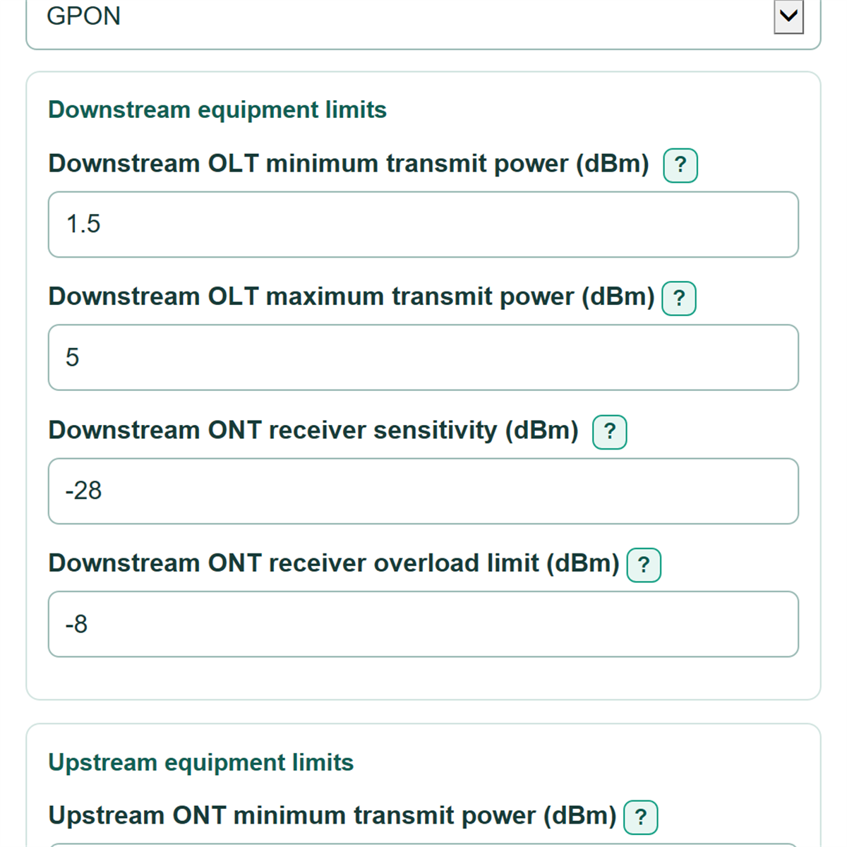
Downstream equipment limits
Upstream equipment limits
Route and main splitter
Advanced options
Fiber assumptions
Optional installed losses
Table of contents
How to use our GPON and XGS-PON Optical Power Budget Calculator
- Choose PON technology, then replace the example transmit and receiver limits with signed dBm values from the exact OLT and ONT data sheets.
- Enter the One-way installed fiber length from an as-built or OTDR record, choose its Fiber-length unit, and include service loops.
- Enter the Main splitter insertion loss and Design reserve in dB. Keep reserve separate from installed component loss.
- Open Advanced options to enter cable attenuation and any second splitter, connector, splice, or other known passive loss.
- Click Calculate. Check that the Weakest receiver-window clearance is positive, then review the named direction and receiver limit controlling the result.
Definitions
dBm: A power level referenced to 1 milliwatt. Optical transmit power and receiver limits use signed dBm values.
dB: A difference or loss value. Fiber, splitters, connectors, splices, reserve, and clearance use dB.
Receiver sensitivity: The weakest optical power a receiver can accept. Predicted minimum receive power must stay above it after reserve.
Receiver overload limit: The strongest optical power a receiver can accept. Predicted maximum receive power must stay below it.
Design reserve: Clearance held back for uncertainty, aging, repairs, contamination, temperature effects, and future changes. It is not installed path loss.
Weakest receiver-window clearance: The smallest of the four checks: downstream sensitivity, downstream overload, upstream sensitivity, and upstream overload. A negative value means at least one limit is missed.
Common mistakes and quick fixes
Mistake: Entering Downstream ONT receiver sensitivity as 28 instead of -28 dBm.
Fix: Copy the signed value from the data sheet. Receiver sensitivity is usually a negative dBm value.
Mistake: Using straight-line map distance for One-way installed fiber length.
Fix: Use the installed OLT-to-ONT cable route, including service loops, from an as-built drawing or OTDR record.
Mistake: Entering a splitter ratio such as 1:32 in Main splitter insertion loss.
Fix: Enter the splitter's insertion loss in dB from its data sheet, such as 17.
Mistake: Counting individual connector ends in Mated connector pairs (optional).
Fix: Count each joined pair of connector ends as one pair, then enter its loss in Loss per mated connector pair (dB).
Mistake: Adding Design reserve into Other known passive loss (dB, optional).
Fix: Keep installed device loss in Other known passive loss (dB, optional) and enter withheld contingency separately as Design reserve.
Mistake: Checking only Downstream sensitivity clearance after reserve.
Fix: Also check both overload clearances and the upstream clearance because the smallest value is the Weakest receiver-window clearance.
Limitations & Key Assumptions / Boundary Conditions
- Results are only as accurate as the entered OLT, ONT, cable, and passive-component specifications. Replace editable examples with values for the exact installed equipment.
- The model uses one total one-way fiber length and one attenuation value per direction. It does not separately model feeder, distribution, drop, or mixed cable types.
- Fiber attenuation, splitter insertion loss, connector loss, splice loss, and other passive loss are treated as additive planning values. Measured loss can differ because of installation quality, bends, contamination, temperature, and wavelength behavior.
- Design reserve is subtracted only from weak-signal clearance. It does not change overload clearance because reserve is withheld margin, not an installed attenuator.
- A pass means the entered minimum and maximum equipment limits fit the modeled receiver windows. Confirm a live circuit with appropriate optical test procedures before service decisions.
- A blank Second splitter-stage loss (dB, optional) means no second physical splitter stage. Enter its data-sheet insertion loss when the route includes one.
Methodology
Calculation method
The calculator converts the entered one-way route to kilometers, adds installed passive losses, and runs separate downstream and upstream checks. Fiber loss is route length in km multiplied by attenuation in dB/km.[1] Connector loss is the entered pair count multiplied by loss per pair.[2]
route_length_km = route_length x selected_unit_to_km
installed_fixed_loss_db = main_splitter_loss + second_splitter_loss + connector_pairs x connector_loss_per_pair + fusion_splices x fusion_splice_loss + other_passive_loss
directional_path_loss_db = route_length_km x directional_attenuation_db_per_km + installed_fixed_loss_db
predicted_receive_power_dbm = transmit_power_dbm - directional_path_loss_db
sensitivity_clearance_db = predicted_min_receive_dbm - receiver_sensitivity_dbm - design_reserve_db
overload_clearance_db = receiver_overload_dbm - predicted_max_receive_dbm
controlling_clearance_db = smallest of the four sensitivity and overload clearances
Worked example
For a 10 km route with 19.1 dB of installed fixed loss, downstream attenuation of 0.25 dB/km gives 21.6 dB downstream path loss. With minimum downstream transmit power of +1.5 dBm, predicted minimum receive power is -20.1 dBm. If ONT sensitivity is -28 dBm and reserve is 3 dB, downstream sensitivity clearance is 4.9 dB. The calculator repeats the same process upstream using its own attenuation and equipment limits.
Calculation scope
Minimum transmit power is used only for weak-signal checks, while maximum transmit power is used only for overload checks. A positive clearance passes that individual check; negative clearance remains negative so the failed direction and receiver limit are visible.