
Enter your DC supply, divider resistors, and load resistance to find the actual output voltage after the load is connected.
Table of contents
How to use our Voltage Divider Load Calculator
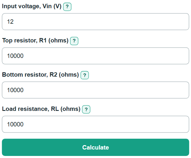
- Enter the DC supply value in "Input voltage, Vin (V)."
- Enter "Top resistor, R1 (ohms)," the resistor connected from Vin to the output node.
- Enter "Bottom resistor, R2 (ohms)," the resistor connected from the output node to ground.
- Enter "Load resistance, RL (ohms)," the fixed resistance connected from the output node to ground. You can type values such as 10000, 10,000, 10k, or 2.2M.
- Select "Calculate." Use "Loaded output voltage" for the connected circuit, then compare it with "Unloaded output voltage" to see how much the load changed it.
- Check the displayed resistor power against each resistor's rated power. The result is for steady DC operation with a fixed resistive load.
Definitions
Voltage divider: Two resistors in series across a voltage source, with an output taken from the node between them.
R1: The top divider resistor, connected from Vin to the output node.
R2: The bottom divider resistor, connected from the output node to ground.
RL: The load resistance connected from the output node to ground.
Parallel resistance: The single effective resistance of R2 and RL when both connect between the same output node and ground.
Loaded output voltage: The steady DC output after RL is connected.
Unloaded output voltage: The divider output before a load is connected.
Voltage lost to loading: The percent by which the load lowers the output compared with the unloaded voltage.
Common mistakes and quick fixes
Mistake: Reversing R1 and R2.
Fix: R1 runs from Vin to the output node. R2 runs from the output node to ground.
Mistake: Using the unloaded divider voltage for a circuit that is already connected.
Fix: Enter the circuit's input resistance as "Load resistance, RL (ohms)" and use "Loaded output voltage."
Mistake: Entering an incorrectly grouped number such as 1,01.
Fix: Use 1000, 1,000, 10k, 4k7, or 2.2M. Commas must separate groups of three digits.
Mistake: Modeling a changing IC input as one fixed resistor.
Fix: Use this calculation only when fixed DC resistance is a suitable model. Check the data sheet for capacitive, sampled, switching, or changing-current input behavior.
Limitations & Key Assumptions / Boundary Conditions
- This calculation assumes a steady DC circuit, positive fixed resistance values, and an ideal input voltage source with zero internal resistance.
- RL is modeled as a constant resistance from the output node to ground. Capacitors, AC impedance, sampled inputs, switching loads, startup behavior, and changing current draw are outside this model.
- Real output voltage can differ because of resistor tolerance, supply variation, wiring resistance, temperature, and the connected circuit's actual input behavior.
- Power values are steady-state estimates. Compare them with the actual resistor rating and allow a suitable design margin.
Methodology
Loaded-divider calculation
RL connects in parallel with R2, so the calculator first finds their combined lower-leg resistance. It then uses that lower-leg resistance with R1 to find the loaded DC output.
Rlower = (R2 * RL) / (R2 + RL)
Vout_loaded = Vin * Rlower / (R1 + Rlower)
The unloaded comparison uses R2 alone as the lower leg.
Vout_unloaded = Vin * R2 / (R1 + R2)
loading_loss_percent = 100 * (Vout_unloaded - Vout_loaded) / Vout_unloaded
Current and power
Current through R1 reaches the output node and splits between R2 and RL. Resistor power uses current squared times resistance or voltage squared divided by resistance.
I_R1_mA = 1000 * Vin / (R1 + Rlower)
I_RL_mA = 1000 * Vout_loaded / RL
P_R1_mW = 1000 * (I_R1_mA / 1000)^2 * R1
P_R2_mW = 1000 * Vout_loaded^2 / R2
P_RL_mW = 1000 * Vout_loaded^2 / RL
Worked example
With Vin = 12 V and R1 = R2 = RL = 10,000 ohms, R2 in parallel with RL is 5,000 ohms. The loaded output is 4.000000 V. The unloaded output is 6.000000 V, so loading lowers it by 33.3333%. Current through R1 is 0.800000 mA, and load current is 0.400000 mA.