
Use this wire gauge calculator to pick the smallest covered conductor size that meets current capacity and voltage drop targets.
Table of contents
How to use our Wire Gauge Calculator
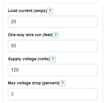
- Enter the Load current (amps), which is the current the load is expected to use.
- Enter the One-way wire run (feet), using the distance from the source to the load, not the full there-and-back path.
- Enter the Supply voltage (volts), Max voltage drop (percent), and Wire material.
- Open Advanced options only if you need to change Circuit type, Continuous load, or Ampacity table column (deg C).
- Click Calculate, then sanity-check the result: Voltage drop should be at or below your Max voltage drop (percent), and Sizing check should explain what kept a thinner size from being selected.
Definitions
AWG: American Wire Gauge, used here for sizes 14 AWG through 4/0 AWG. A smaller AWG number means a thicker conductor.
kcmil: A conductor-area unit used for the larger covered sizes. For example, 350 kcmil means 350,000 circular mils.
Load current (amps): The current the connected load is expected to draw. Current is measured in amps.
One-way wire run (feet): The distance from the power source to the load. The calculator applies the needed path factor for the selected Circuit type.
Voltage drop: The voltage lost in the wire before power reaches the load. The output shows both percent and volts.
Ampacity: The current a conductor is allowed to carry in the selected table column before extra project-specific adjustments.
Continuous load: A load expected to run for 3 hours or more. When set to Yes, the ampacity check uses 125 percent of Load current (amps).
Circuit type: The wiring arrangement used for the voltage drop formula, either 2-wire DC or 1-phase AC, or balanced 3-phase AC.
Circular mil: A wire area unit based on conductor diameter in mils, where 1 mil is 0.001 inch.
Common mistakes and quick fixes
Mistake: Entering the full loop distance in One-way wire run (feet).
Fix: Enter only the source-to-load distance; the calculator handles the return path for Voltage lost in the wire.
Mistake: Using Load current (amps) from a guess instead of the equipment label or design load.
Fix: Use the expected running current, or get a qualified electrician to confirm it before trusting Recommended wire size.
Mistake: Setting Max voltage drop (percent) too high just to get a thinner Recommended wire size.
Fix: Use a design limit that your equipment can tolerate; lower values usually require thicker wire.
Mistake: Leaving Continuous load set to No when the load is expected to run for 3 hours or more.
Fix: Set Continuous load to Yes, size ampacity at 125 percent so Current used for ampacity check matches that sizing rule.
Mistake: Choosing the wrong Wire material, especially copper when the installed conductor is aluminum.
Fix: Match Wire material to the actual conductor so Voltage drop and Table ampacity for selected wire are checked against the right data.
Mistake: Treating Ampacity table column (deg C) as a way to bypass equipment limits.
Fix: Use the temperature column allowed by the wire insulation and terminals, and do not treat Result summary as a full code approval.
Limitations & Key Assumptions / Boundary Conditions
- This is a sizing estimate, not proof that an installation meets electrical code.
- The covered wire sizes are 14 AWG through 4/0 AWG plus 250, 300, 350, 400, and 500 kcmil. If none pass, the result shows the largest covered size and the binding check, but the job still needs a different design or qualified review.
- The ampacity check uses a simplified copper or aluminum table subset and the selected Ampacity table column (deg C). It does not apply terminal limits, ambient temperature correction, bundled-conductor derating, conduit fill, or local code changes.
- Voltage drop uses conductor resistance constants near 20 deg C. Hot conductors have more resistance, so real voltage drop can be higher.
- Motor starting current, inrush current, power factor details, harmonic current, insulation type, and installation method are not modeled.
- For voltage drop, the calculator uses the entered Load current (amps). It does not multiply current by 125 percent unless you enter that higher current yourself.
- Balanced 3-phase results assume the load is balanced. Do not use that option for an unbalanced 3-phase circuit.
Methodology
How the wire size is chosen
The calculator tests the covered wire sizes from smallest physical conductor to largest. A size is selected only when it passes both checks: its table ampacity is at least the design current, and its voltage drop percent is at or below the entered limit. This matches the practical idea that wire selection should account for current capacity and voltage drop over distance [1]. The 60, 75, and 90 deg C table values are taken from the published conductor ampacity table in source [3].
diameter_in = 0.005 * 92^((36 - awg_number) / 39)
area_cmil = (1000 * diameter_in)^2
For 1/0 through 4/0 sizes, the calculator uses the AWG diameter formula and displays slash-zero labels. For 250 through 500 kcmil, it uses the stated circular-mil area directly.
Voltage drop math
The calculator uses copper K = 10.371 ohm-cmil/ft or aluminum K = 16.782 ohm-cmil/ft. It uses actual Load current (amps) for voltage drop.
two_wire_vdrop = 2 * K * load_current * one_way_length_ft / area_cmil
three_phase_vdrop = sqrt(3) * K * load_current * one_way_length_ft / area_cmil
voltage_drop_percent = 100 * voltage_drop_volts / supply_voltage
voltage_at_load = supply_voltage - voltage_drop_volts
If voltage drop is critical, using a larger wire can be the safer design choice [2].
Ampacity and heat loss math
When Continuous load is No, the design current equals the entered load current. When Continuous load is Yes, the ampacity check uses 125 percent of the entered load current.
design_current_amps = load_current * 1.25 when continuous_load is yes
design_current_amps = load_current when continuous_load is no
two_wire_power_loss_watts = load_current * voltage_drop_volts
three_phase_power_loss_watts = sqrt(3) * load_current * voltage_drop_volts
Worked mini-example
For 20 amps, 50 feet one way, 120 volts, copper, 3 percent maximum voltage drop, 2-wire circuit, no continuous-load adder, and the 75 deg C column, the calculator selects 12 AWG. Its estimated voltage lost in the wire is about 3.18 V, voltage drop is about 2.65 percent, estimated voltage at the load is about 116.82 V, table ampacity is 20 amps, and estimated power lost as heat is about 63.5 W. The next thinner wire is not picked because it does not pass the combined checks.