
Use this pull-down resistor calculator to choose a value that keeps a digital input low without wasting too much current.
Advanced options
Table of contents
How to use our Pull Down Resistor Calculator
- Enter the Signal high voltage (V), usually the logic high voltage on the pin, such as 3.3 V or 5 V.
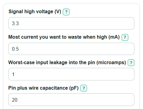
- Enter the Most current you want to waste when high (mA), Worst-case input leakage into the pin (microamps), Pin plus wire capacitance (pF), and Time allowed to read low (microseconds).
- Open Advanced options only if you need to change the Safe low level (percent of high voltage), Resistor values to choose from, Safety room below the limits (percent), or check a part in Resistor you already have (ohms).
- Click Calculate, then read Design check first and Recommended pull-down resistor next.
- Sanity-check the details: Current when the signal is high should be within your power budget, Time to fall to a safe low should be no more than the time allowed, and Low voltage caused by leakage should be below the safe-low voltage.
Definitions
Pull-down resistor: A resistor from the signal line to ground. It makes the input read low when no switch, sensor, or chip is actively driving the line.
Signal high voltage (V): The voltage on the signal when another device drives it high.
Worst-case input leakage into the pin (microamps): Small unwanted current that can flow into an input pin. Through a large pull-down resistor, this current can raise the idle voltage.
Pin plus wire capacitance (pF): Stored electric charge on the input, wire, and connected parts. More capacitance makes the signal fall more slowly.
Safe low level (percent of high voltage): The highest voltage that still counts as a clear logic low for this calculation.
E12, E24, and E96: Standard resistor value sets. E12 has fewer values per decade, E24 has more, and E96 has many precision values.
Safety room below the limits (percent): Extra space below the calculated upper resistor limit before the calculator chooses a standard value.
Common mistakes and quick fixes
Mistake: Using the board supply for Signal high voltage (V) when the signal is actually driven by a lower-voltage chip.
Fix: Enter the voltage that appears on that signal when it is high, not just the highest voltage on the board.
Mistake: Leaving Worst-case input leakage into the pin (microamps) at a guess for a final design.
Fix: Use the worst-case leakage from the input pin datasheet, including temperature if the product may get hot or cold.
Mistake: Entering only the chip pin capacitance in Pin plus wire capacitance (pF) for a long wire or large sensor pad.
Fix: Include the pin, wire, connector, sensor, and any other capacitance connected to the signal.
Mistake: Setting Time allowed to read low (microseconds) much faster than the code or circuit actually needs.
Fix: Use the real time between the high driver letting go and the next read; a looser time can allow a higher resistor and lower current.
Mistake: Choosing a very high Safety room below the limits (percent) and then wondering why no standard value passes.
Fix: Try a smaller safety room, E96 in Resistor values to choose from, or relax the current, leakage, or timing limits.
Mistake: Treating Your resistor check as a replacement for Design check.
Fix: Use Recommended pull-down resistor for a first choice, then use Resistor you already have (ohms) only to test a specific part value.
Limitations & Key Assumptions / Boundary Conditions
- The result is a first-pass resistor choice for a simple pull-down on a digital input. It does not replace the input, output, and timing limits in the device datasheets.
- The leakage check assumes the leakage current flows in the direction that lifts the pull-down node upward. If your part can leak in both directions, use the worst case that hurts the low level.
- The settling-time check uses a simple resistor-capacitor discharge model. Real signals can differ because of driver resistance, protection diodes, cable effects, switch bounce, noise, and PCB layout.
- If Pin plus wire capacitance (pF) is entered as 0, the timing upper-limit check is skipped. If Worst-case input leakage into the pin (microamps) is entered as 0, the leakage upper-limit check is skipped.
- The recommended value is limited to the selected standard resistor series. A real resistor tolerance, such as 1 percent or 5 percent, can move the actual resistance above or below the listed value.
- Very low resistor values can load the high-driving device. Check the device output-current rating before using a small resistor in hardware.
Methodology
How the range is found
The calculator first finds the smallest resistor allowed by your current limit. A pull-down resistor that is too small wastes current whenever the signal is high.
R_min = V_high / (I_max_mA / 1000)
Next it converts the safe-low percentage into a voltage.
V_low_max = V_high * (low_threshold_percent / 100)
Leakage sets one upper limit. If leakage is zero, this upper limit is skipped so the calculator does not divide by zero.
R_max_leak = V_low_max / (I_leak_uA * 0.000001)
Settling time sets another upper limit. The model is the normal capacitor discharge equation rearranged to solve for resistance.
R_max_time = t_allowed_s / (C_farad * ln(V_high / V_low_max))
The hard upper limit is the smaller of the leakage and timing limits. The target upper limit applies the safety-room setting.
R_max_hard = min(R_max_leak, R_max_time)
R_max_target = R_max_hard * (1 - margin_percent / 100)
How the recommendation is chosen
The calculator builds standard values from the selected E12, E24, or E96 series, then chooses the largest value that is at least R_min and no more than R_max_target. The largest passing resistor is chosen because it wastes the least current while still passing the checks.
R_pick = largest standard value where R_min <= R_pick <= R_max_target
For the chosen resistor, or for Resistor you already have (ohms), the calculator reports current, power, leakage voltage, and fall time.
I_high_mA = (V_high / R) * 1000
P_high_mW = (V_high * V_high / R) * 1000
V_leak = I_leak_uA * 0.000001 * R
t_fall_us = R * C_farad * ln(V_high / V_low_max) * 1000000
Worked mini-example
With Signal high voltage (V) = 3.3, Most current you want to waste when high (mA) = 0.5, Worst-case input leakage into the pin (microamps) = 1, Pin plus wire capacitance (pF) = 20, Time allowed to read low (microseconds) = 1, Safe low level (percent of high voltage) = 30, and Safety room below the limits (percent) = 20, the minimum resistor is 6600 ohms. The safe-low voltage is 0.99 V. The timing limit is about 41529 ohms, which is tighter than the leakage limit, so the target maximum is about 33224 ohms. In E24, the largest passing value is 33000 ohms. At 33000 ohms, current when high is 0.1 mA, resistor power is 0.33 mW, fall time is about 0.795 microseconds, and leakage raises the low voltage by about 0.033 V.