
Enter a PCB trace's length, width, and copper specification to calculate its estimated DC resistance, plus voltage drop and power loss if you enter current.
Table of contents
How to use our PCB Trace Resistance Calculator
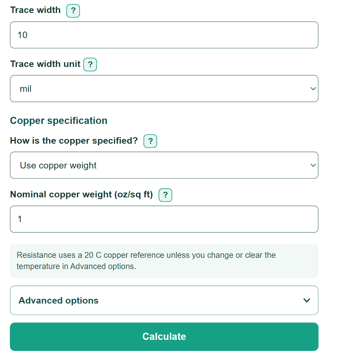
- Enter the routed centerline length and finished trace width, then choose the units shown in your PCB layout tool.
- Under "How is the copper specified?", choose "Use copper weight" for oz/sq ft or "Use finished thickness" for a physical stackup thickness.
- Open "Advanced options" to change copper temperature or enter load current when you also need voltage drop and copper power loss.
- Select "Calculate" and read "DC trace resistance" first. Check that "Copper thickness used" matches the thickness in your board specification before using the estimate.
Definitions
DC resistance: Opposition to steady direct current. This calculator reports it in milliohms (mOhm), where 1,000 mOhm equals 1 ohm.
Copper weight: A PCB copper convention stated in oz/sq ft. This calculator converts 1 oz/sq ft to a nominal thickness of 35 um.
Finished copper thickness: The physical copper thickness in a board stackup, such as 17.5 um, 18 um, or 35 um.
Mil: One thousandth of an inch, equal to 0.0254 mm. PCB trace widths are often stated in mil.
Voltage drop: Voltage lost across the entered trace when current flows through its resistance.
Copper power loss: Electrical power turned into heat in the modeled trace because of its resistance.
Common mistakes and quick fixes
Mistake: Using the straight-line distance between components instead of the routed path length.
Fix: Copy the routed centerline length from the PCB layout tool.
Mistake: Entering a width in mil while "Trace width unit" is set to mm.
Fix: Set each unit selector to match the number you copied, or change the selector before entering the measurement.
Mistake: Treating nominal copper weight as a measured finished thickness.
Fix: Choose "Use copper weight" for oz/sq ft, or choose "Use finished thickness" and enter the physical thickness from the stackup.
Mistake: Using ambient air temperature as copper temperature without knowing the trace temperature.
Fix: Enter an estimated or measured conductor temperature. A blank temperature uses the 20 C reference condition.
Mistake: Assuming a low voltage drop proves the trace can safely carry the current.
Fix: Check thermal current capacity separately because this calculation does not predict trace temperature.
Mistake: Leaving out vias, connectors, pads, or the return path in a full-path voltage-drop check.
Fix: Calculate each important section or use a complete circuit-path resistance model.
Limitations & Key Assumptions / Boundary Conditions
- The calculation models one uniform rectangular copper trace with the entered length, width, and thickness.
- It excludes vias, pads, solder joints, connectors, plane spreading resistance, and the return-path resistance.
- The copper-weight method uses a nominal 35 um per oz/sq ft convention. Use finished thickness when the fabricator states a physical value.
- The temperature adjustment uses a linear copper-resistance correction from a 20 C reference. Actual conductor temperature can vary along a loaded trace.
- Voltage drop and copper power loss apply only when the entered current flows through the entire modeled trace.
- This is a DC resistance estimate. It does not calculate AC skin effect, surface-roughness effects, impedance, or thermal current capacity.
Methodology
Calculation method
The calculator converts length, width, and copper thickness to meters. It starts with copper resistivity of 1.7241e-8 ohm*m at 20 C, then adjusts it using a temperature coefficient of 0.00393 per C.
ρ_T = ρ_20 (1 + α(T - 20))
ρ_T is copper resistivity at the entered temperature, ρ_20 is resistivity at 20 C, α is the temperature coefficient, and T is copper temperature in C.
R = ρ_T L / (W t)
R is resistance in ohms, L is trace length in meters, W is trace width in meters, and t is copper thickness in meters. The calculator multiplies R by 1,000 to display mOhm.
Vdrop = I R
Ploss = I^2 R
I is load current in amperes. Voltage drop is displayed in mV, and copper power loss is displayed in mW.
Worked example
A 100 mm trace that is 10 mil wide with 1 oz/sq ft nominal copper uses 35 um thickness. At 20 C, its estimated resistance is 193.9370 mOhm. With 2 A through the trace, the estimated voltage drop is 387.8740 mV and copper power loss is 775.7480 mW.
Copper specification choice
The copper-weight method multiplies oz/sq ft by 35 um. The finished-thickness method uses the entered thickness directly, so 17.5 um and 18 um produce different resistance estimates. A blank copper-temperature field uses 20 C, while a blank load-current field leaves voltage-drop and power-loss results unavailable.