
Calculate non-inverting op amp gain, ideal output voltage, needed resistor values, and simple rail checks.
Advanced options
Table of contents
How to use our Non Inverting Op Amp Calculator
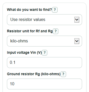
- Choose What do you want to find?: Use resistor values, Find feedback resistor Rf, or Find ground resistor Rg.
- Pick Resistor unit for Rf and Rg, then enter Input voltage Vin plus the resistor or Target gain fields shown for your choice.
- Open Advanced options if you want the Supply rail check, Estimated load current, or Estimated bandwidth to use your real circuit values.
- Click Calculate and read Ideal output voltage first, then check Voltage gain, Gain in dB, and any Needed feedback resistor Rf or Needed ground resistor Rg result.
- Sanity-check the answer: if Supply rail check says the output is outside the usable range, lower Input voltage Vin or Voltage gain, or use wider supply rails.
Definitions
Non-inverting op amp: An op amp circuit where the signal enters the plus input, so the output keeps the same polarity as the input.
Feedback resistor Rf: The resistor from the output back to the minus input. A larger Rf usually raises Voltage gain.
Ground resistor Rg: The resistor from the minus input to ground or another reference point. It works with Rf to set the gain.
Voltage gain: The output voltage divided by the input voltage, shown as V/V. A gain of 11 means 0.1 V ideally becomes 1.1 V.
Gain in dB: The same voltage gain on a decibel scale, using 20 times the base-10 log of the voltage ratio.
Supply rail: A power-supply limit for the op amp. Positive supply rail is the high limit, and Negative supply rail is the low limit.
Output headroom from each rail: The distance the real output may need to stay away from each supply rail.
Feedback fraction: The part of the output voltage fed back to the minus input, equal to 1 divided by Voltage gain for this ideal circuit.
Gain-bandwidth product: A datasheet number used for a rough small-signal bandwidth estimate by dividing it by Voltage gain.
Common mistakes and quick fixes
Mistake: Entering Rf and Rg in different units while Resistor unit for Rf and Rg applies to both.
Fix: Convert both Feedback resistor Rf and Ground resistor Rg to the same unit before you calculate.
Mistake: Using Target gain below 1 for a standard non-inverting amplifier.
Fix: Enter Target gain as 1 or higher, because this resistor-set circuit cannot make a gain below 1.
Mistake: Swapping Feedback resistor Rf and Ground resistor Rg.
Fix: Put the resistor from output to the minus input in Feedback resistor Rf, and the resistor from the minus input to ground or reference in Ground resistor Rg.
Mistake: Trusting Ideal output voltage without checking the power supplies.
Fix: Enter Positive supply rail, Negative supply rail, and Output headroom from each rail, then read Supply rail check.
Mistake: Entering Load resistance to ground as 0 or leaving a typed non-number in the box.
Fix: Leave Load resistance to ground blank if unknown, or enter a positive resistance in ohms.
Mistake: Treating Estimated bandwidth as a guaranteed frequency limit.
Fix: Use Op amp gain-bandwidth product only as a rough check, then verify the datasheet for your exact op amp and load.
Limitations & Key Assumptions / Boundary Conditions
- The formulas model an ideal standard non-inverting amplifier. Real op amps have input offset voltage, bias current, finite open-loop gain, noise, and output-current limits.
- Supply rail check uses Positive supply rail, Negative supply rail, and one Output headroom from each rail value. Real output swing depends on the exact op amp, load, temperature, and supply voltage.
- Estimated load current assumes Load resistance to ground. Other load connections need a different current calculation.
- Estimated bandwidth uses Op amp gain-bandwidth product divided by Voltage gain. It is a rough small-signal estimate, not a full stability or slew-rate check.
- Needed feedback resistor Rf and Needed ground resistor Rg are ideal values. Real resistor tolerance and nearest standard resistor values change the actual gain.
- For Target gain equal to 1, Needed feedback resistor Rf can be 0 in the ideal voltage-follower case. Finding a finite Needed ground resistor Rg from that target is not defined by the divider formula.
Methodology
Core gain calculation
The calculator first converts Feedback resistor Rf and Ground resistor Rg to ohms using the selected Resistor unit for Rf and Rg. The standard non-inverting gain is:
A_v = 1 + (Rf / Rg)
Then it multiplies the gain by Input voltage Vin to get the ideal output:
Vout = Vin * A_v
Gain in dB is calculated from the voltage ratio:
Gain_dB = 20 * log10(abs(A_v))
Solving for a resistor
If you choose Find feedback resistor Rf, the calculator rearranges the gain formula:
Rf = (A_v_target - 1) * Rg
If you choose Find ground resistor Rg, it uses:
Rg = Rf / (A_v_target - 1)
The feedback fraction is also reported:
beta = Rg / (Rf + Rg) = 1 / A_v
Practical checks
The usable output range is estimated by moving inward from each supply rail by the entered headroom:
V_high_limit = V_pos - Headroom
V_low_limit = V_neg + Headroom
The margins show how far the ideal output is from those limits:
Margin_high = V_high_limit - Vout
Margin_low = Vout - V_low_limit
If Load resistance to ground is entered, current is:
I_load = Vout / R_load
If Op amp gain-bandwidth product is entered, bandwidth is estimated as:
Bandwidth = GBW / A_v
Mini-example
With Feedback resistor Rf = 100 kohm, Ground resistor Rg = 10 kohm, and Input voltage Vin = 0.1 V, the gain is 1 + 100/10 = 11 V/V. The ideal output is 0.1 * 11 = 1.1 V. With 5 V and 0 V rails and 0.2 V headroom, the usable range is 0.2 V to 4.8 V, so 1.1 V is inside the estimated range.