
Calculate a standard 555 astable timer, where the output keeps switching on and off by itself.
Table of contents
How to use our 555 Astable Timer Calculator
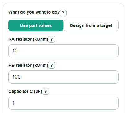
- Choose What do you want to do?: use part values if you know RA resistor, RB resistor, and Capacitor C, or design from a target if you know the Target frequency and Target on time you want.
- Enter the visible values in the units shown, such as kOhm for resistors, uF for the capacitor, Hz for Target frequency, and percent for Target on time.
- Open Advanced options only if you want a likely frequency range from RA tolerance, RB tolerance, and Capacitor tolerance.
- Click Calculate and read Output frequency first, then check Time for one full cycle, Output high time, High time, and Low time.
- Sanity-check the answer: in the standard two-resistor astable circuit, Output high time should be more than 50 percent, and a larger Capacitor C or larger resistor usually means a lower Output frequency.
Definitions
Astable: A 555 mode where the output changes high and low over and over without an outside trigger.
RA resistor: The timing resistor from the supply side to the discharge pin in the common 555 astable circuit.
RB resistor: The timing resistor between the discharge pin and the capacitor node.
Capacitor C: The timing capacitor that charges and discharges to set the switching speed.
Output frequency: The number of full high-low cycles each second, measured in hertz (Hz) [3].
Time for one full cycle: One complete high time plus one complete low time, measured in seconds.
Output high time: The percent of each cycle where the 555 output is high.
Tolerance: The allowed part-value error from the marked value, usually shown as a percent.
Common mistakes and quick fixes
Mistake: Entering RA resistor or RB resistor in ohms when the field expects kOhm.
Fix: Divide ohms by 1000 before entering RA resistor or RB resistor.
Mistake: Using nF or pF directly in Capacitor C when the field expects uF.
Fix: Convert first, such as 10 nF = 0.01 uF, then enter Capacitor C.
Mistake: Setting Target on time to 50 percent or less in design mode.
Fix: Use a Target on time greater than 50 percent, or use a different 555 circuit if you need 50 percent or less.
Mistake: Filling RA tolerance but leaving RB tolerance or Capacitor tolerance blank.
Fix: Fill all three tolerance fields, or clear all three to skip Lowest likely frequency and Highest likely frequency.
Mistake: Treating Output frequency as an exact measured value.
Fix: Check Lowest likely frequency and Highest likely frequency when tolerances are known, then test the real circuit.
Limitations & Key Assumptions / Boundary Conditions
- This calculator uses the standard two-resistor 555 astable circuit. It does not model diode duty-cycle tricks, divider circuits, CMOS-specific changes, or monostable operation.
- Design mode only works for Target on time greater than 50 percent and less than 100 percent. The basic circuit would need zero or negative resistance outside that range.
- Real timing can differ because resistor tolerance, capacitor tolerance, capacitor leakage, breadboard wiring, supply voltage behavior, and the exact 555 part all matter.
- The tolerance range assumes the worst simple case: high part values give the Lowest likely frequency, and low part values give the Highest likely frequency.
- Very small resistor values can overload the discharge transistor, and very large resistor values can make leakage current matter. Check the datasheet for your 555 part before building near extremes.
- The results assume RA resistor and RB resistor are positive, Capacitor C is positive, and the capacitor value is the actual capacitance in uF.
Methodology
How the part-value calculation works
The calculator treats RA and RB as ohms and Capacitor C as farads after converting from kOhm and uF. It uses ln(2) instead of the rounded 0.693 shortcut. For the standard 555 astable circuit, the capacitor charges through RA and RB during the high part of the cycle and discharges through RB during the low part [1].
t_high = ln(2) * (RA + RB) * C
t_low = ln(2) * RB * C
period = t_high + t_low = ln(2) * (RA + 2 * RB) * C
frequency = 1 / period
duty_percent = 100 * (RA + RB) / (RA + 2 * RB)
How design mode works
Design mode starts with a target frequency, a target high-time fraction, and a chosen capacitor. It solves the same equations backward to find RA and RB.
K = 1 / (ln(2) * frequency * C)
RA = K * (2 * duty_fraction - 1)
RB = K * (1 - duty_fraction)
This solve is accepted only when duty_fraction is greater than 0.5 and less than 1, because positive RA and RB in the standard circuit make Output high time greater than 50 percent.
How the tolerance range works
When RA tolerance, RB tolerance, and Capacitor tolerance are all filled, the calculator gives a simple worst-case frequency range.
f_low = 1 / (ln(2) * (RA * (1 + tol_RA) + 2 * RB * (1 + tol_RB)) * C * (1 + tol_C))
f_high = 1 / (ln(2) * (RA * (1 - tol_RA) + 2 * RB * (1 - tol_RB)) * C * (1 - tol_C))
Mini example
With RA resistor = 10 kOhm, RB resistor = 100 kOhm, and Capacitor C = 1 uF, the converted values are RA = 10000 ohms, RB = 100000 ohms, and C = 0.000001 F. The calculator gets High time = 0.076246 s, Low time = 0.069315 s, Time for one full cycle = 0.145561 s, Output frequency = 6.86998 Hz, and Output high time = 52.381 percent.