
Find an LC filter cutoff, solve for the missing part, and check how tolerances can move the result.
Table of contents
How to use our LC Filter Calculator
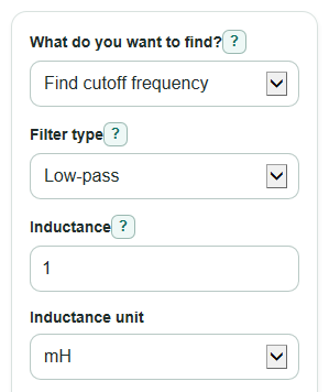
- Choose What do you want to find?: Cutoff frequency, Needed inductance, or Needed capacitance.
- Pick the Filter type, then enter the part values and units that match your labels, such as mH, uH, nF, or pF.
- If you are solving for a part, enter the Target cutoff frequency and the known part value.
- Open Advanced options if you want a Possible cutoff range from part tolerance or a Signal frequency to check.
- Sanity-check the answer by looking at the units, the LC ohms value, and whether the cutoff is close to the range you expected.
Definitions
Cutoff frequency: The ideal boundary frequency from the inductor and capacitor values. In this calculator it is shown as Hz, kHz, or MHz.
Inductance: The L value of the inductor. Common units are H, mH, uH, and nH.
Capacitance: The C value of the capacitor. Common units are F, uF, nF, and pF.
LC ohms value: The value sqrt(L / C), shown in ohms. It is a useful scale for comparing the inductor and capacitor at the cutoff.
Reactance: The AC opposition of an inductor or capacitor, measured in ohms. Each part reactance at cutoff should match in the ideal LC calculation.
Part tolerance: How far a real part may be from its marked value, written as a percent such as 10 percent.
Signal compared with cutoff: The signal frequency divided by the cutoff frequency. Under 1 is below cutoff, and over 1 is above cutoff.
Common mistakes and quick fixes
Mistake: Entering Inductance as 100 but leaving Inductance unit set to mH when the part is 100 uH.
Fix: Match Inductance unit to the part marking before you trust Cutoff frequency.
Mistake: Mixing up Capacitance unit values, especially uF, nF, and pF.
Fix: Recheck Capacitance and Capacitance unit; 1 uF equals 1000 nF and 1000000 pF.
Mistake: Choosing What do you want to find? as Needed inductance or Needed capacitance, then forgetting Target cutoff frequency.
Fix: Enter a Target cutoff frequency greater than 0 and choose the correct Target cutoff unit.
Mistake: Leaving Inductor tolerance (percent) or Capacitor tolerance (percent) blank.
Fix: Enter a number from 0 up to, but not including, 100 so Possible cutoff range from part tolerance can be calculated.
Mistake: Treating Signal compared with cutoff as exact attenuation.
Fix: Use Signal frequency to check only to see which side of the cutoff the signal is on.
Mistake: Picking the wrong Filter type and reading Signal side for this filter backward.
Fix: Use Low-pass when lower frequencies are meant to pass, and High-pass when higher frequencies are meant to pass.
Limitations & Key Assumptions / Boundary Conditions
- This is an ideal LC calculation. It does not model source resistance, load resistance, inductor winding resistance, capacitor ESR, or wiring effects.
- The cutoff range uses only the entered Inductor tolerance (percent) and Capacitor tolerance (percent). Temperature, aging, DC bias, and part series are not included.
- Low-pass and High-pass use the same ideal cutoff math here. The Filter type only changes the pass-side interpretation.
- Signal frequency to check gives a direction check only. It does not calculate real attenuation, phase shift, ripple, or Q.
- At very high frequencies, lead length and board layout can add stray inductance and capacitance that move the real cutoff.
- Needed inductance and Needed capacitance may not be standard stocked part values. Choose a real part close to the answer and recalculate.
Methodology
Core calculation
The calculator first converts all entered values to base units: inductance to henries, capacitance to farads, and frequency to hertz. It then uses the ideal LC cutoff formula.
f_c = 1 / (2 * π * sqrt(L * C))
In this formula, f_c is cutoff frequency in hertz, L is inductance in henries, and C is capacitance in farads.
Solving backward
When you choose Needed inductance, the calculator rearranges the same formula to solve for L.
L = 1 / ((2 * π * f_c)^2 * C)
When you choose Needed capacitance, it solves for C instead.
C = 1 / ((2 * π * f_c)^2 * L)
Ohms and reactance
The LC ohms value is calculated from the ratio of the two parts.
Z0 = sqrt(L / C)
The calculator also checks each part reactance at the cutoff.
X_L = 2 * π * f_c * L
X_C = 1 / (2 * π * f_c * C)
For the ideal LC result, X_L and X_C have the same magnitude, except for rounding.
Tolerance range and signal check
For the low end of the cutoff range, the calculator uses the largest allowed L and C values. For the high end, it uses the smallest allowed L and C values.
f_c_min = 1 / (2 * π * sqrt((L * (1 + tL)) * (C * (1 + tC))))
f_c_max = 1 / (2 * π * sqrt((L * (1 - tL)) * (C * (1 - tC))))
Here, tL and tC are tolerance fractions, so 10 percent is used as 0.10. The signal check divides the test signal frequency by the cutoff.
ratio = f_test / f_c
Mini-example
With Inductance = 1 mH and Capacitance = 1 uF, the calculator uses L = 0.001 H and C = 0.000001 F.
f_c = 1 / (2 * π * sqrt(0.001 * 0.000001)) = 5032.92 Hz
That displays as about 5.03 kHz. The LC ohms value is sqrt(0.001 / 0.000001), or about 31.62 ohms. With a 10 kHz test signal, the ratio is about 1.99 times cutoff.