
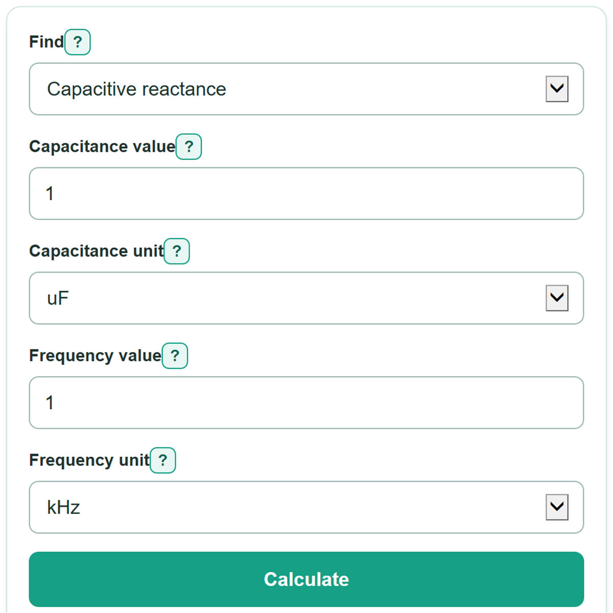
Enter capacitance and frequency to find ideal capacitive reactance, or choose a different unknown to calculate the capacitance or frequency needed.
A larger value means the ideal capacitor opposes more AC current at this frequency. At 0 Hz, ideal reactance is infinite.
This is an ideal target. Real capacitors have tolerance and other non-ideal behavior.
This is the ideal frequency where the entered capacitance has the target reactance.
Table of contents
How to use our Capacitive Reactance Calculator
- Choose what to find: capacitive reactance, required capacitance, or required frequency.
- Enter the two known values, then choose the unit shown on the capacitor marking, schematic, signal source, or circuit requirement.
- Click Calculate. The answer is automatically shown in a readable scale, such as ohms, kilohms, microfarads, or kilohertz.
- Check the prefixes before using the answer: 1 uF equals 1,000 nF, and 1 kHz equals 1,000 Hz.
- For a real circuit, use the result as an ideal starting point and check the selected capacitor's tolerance and non-ideal specifications.
Definitions
Capacitive reactance (Xc): An ideal capacitor's opposition to alternating current (AC), measured in ohms.
Capacitance (C): A capacitor's ability to store electric charge, measured in farads (F). Common units include microfarads (uF), nanofarads (nF), and picofarads (pF).
Frequency (f): The number of AC cycles per second, measured in hertz (Hz). One kilohertz (kHz) is 1,000 Hz.
Target reactance: The desired Xc value used when calculating a required capacitance or frequency. It is not the total impedance of a circuit.
Impedance: Total opposition to AC in a circuit. It can include resistance and reactance from capacitors and inductors.
DC: Direct current at 0 Hz. In the ideal steady-state model, a capacitor has infinite capacitive reactance at DC. [1]
Common mistakes and quick fixes
Mistake: Entering a value marked uF while selecting nF.
Fix: Select the exact prefix shown with the value. For example, 1 uF is 1,000 nF, not 1 nF.
Mistake: Entering 1 for a 1 kHz signal while Frequency unit is set to Hz.
Fix: Select kHz for an entry of 1, or enter 1000 with Hz selected.
Mistake: Using a circuit's total impedance as the target reactance.
Fix: Enter only the capacitor's target Xc value. Resistance, inductance, and other circuit effects are outside this ideal calculation.
Mistake: Treating 0 Hz as ordinary AC.
Fix: In capacitive reactance mode, 0 Hz is the DC boundary, so an ideal capacitor has infinite reactance. Reverse calculations require a frequency greater than 0.
Mistake: Choosing a capacitor by the calculated value alone.
Fix: Select a nearby available part, then recalculate with its marked capacitance and check its tolerance, voltage rating, and frequency behavior.
Limitations & Key Assumptions / Boundary Conditions
- This calculation uses an ideal capacitor model and does not include equivalent series resistance, leakage, dielectric loss, lead inductance, or self-resonance.
- A capacitor's actual capacitance can differ from its marked value because of tolerance, temperature, voltage, and aging.
- Capacitive reactance is not total circuit impedance. Resistors, inductors, source resistance, loads, and circuit layout affect actual current and voltage.
- At 0 Hz, the calculator reports infinite reactance only for an ideal capacitor in steady state. A real capacitor can have leakage current and a temporary charging current.
- Capacitance and target reactance must be positive. Reverse calculations also require a frequency greater than 0.
Methodology
Ideal capacitor equation
The calculator converts the selected capacitance prefix to farads and the selected frequency prefix to hertz, then applies the ideal capacitive reactance equation. [1]
Xc = 1 / (2πfC)
Xc is capacitive reactance in ohms, f is frequency in hertz, and C is capacitance in farads. Increasing frequency or capacitance decreases ideal reactance.
Finding a missing value
For a target reactance, the calculator rearranges the same relationship.
C = 1 / (2πfXc)
f = 1 / (2πCXc)
Worked example
For a 1 uF capacitor at 1 kHz, the calculator uses 0.000001 F and 1000 Hz. Dividing 1 by 2 times pi times 1000 times 0.000001 gives 159.154943... ohms, displayed as about 159.2 ohms.
Calculation boundaries
The formula requires positive capacitance. In forward mode, 0 Hz is handled as the DC boundary and returns infinite ideal reactance instead of dividing by zero. Finding a finite capacitance or frequency requires both frequency and target reactance to be greater than 0.