
Enter your crossover frequency and each driver's impedance to calculate passive two-way crossover parts, circuit order, and a starting polarity connection.
Table of contents
How to use our Speaker Crossover Calculator
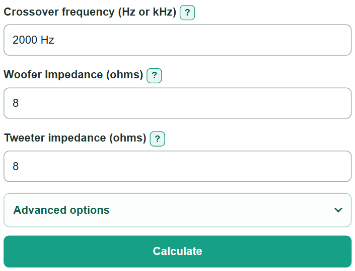
- Enter the planned crossover frequency in Hz or kHz. A number with no unit is treated as Hz.
- Enter the woofer and tweeter impedance separately. Use measured impedance near the crossover frequency when available; otherwise use each driver's nominal impedance.
- Open "Advanced options" to choose the electrical filter or compare the exact values with nearby E12 or E24 parts.
- Click "Calculate" and install each part in the circuit order shown. Follow the starting driver-polarity instruction.
- Sanity-check the result before buying parts: confirm each branch uses the correct driver impedance, and remember that a standard part value is a substitution, not the exact calculated value.
Definitions
Crossover frequency: The target frequency where the woofer low-pass branch and tweeter high-pass branch meet electrically.
Impedance (ohms): A driver's opposition to alternating current. It changes with frequency, so nominal impedance is only a first estimate.
Low-pass filter: The woofer branch, which reduces higher-frequency electrical signal sent to the woofer.
High-pass filter: The tweeter branch, which reduces lower-frequency electrical signal sent to the tweeter.
First-order filter: A 6 dB per octave electrical filter with one part in each driver branch.
Second-order filter: A 12 dB per octave electrical filter with two parts in each driver branch.
Branch return: The common return wire for one crossover branch, usually connected to the amplifier negative connection.
E12 and E24: Preferred-number series used for commonly stocked component values. They approximate the exact calculated values.
Common mistakes and quick fixes
Mistake: Using the woofer impedance for both crossover branches.
Fix: Enter the woofer and tweeter impedance separately. Each branch gets different part values when the impedances differ.
Mistake: Entering DC resistance instead of impedance.
Fix: Use nominal impedance or measured impedance near the crossover frequency. DC resistance is a different measurement.
Mistake: Typing "2 MHz" when the target is 2 kHz.
Fix: Use Hz or kHz only, such as "2000 Hz" or "2 kHz".
Mistake: Treating the nearest E12 or E24 value as the exact calculated part.
Fix: Use the standard-part value as a purchasing comparison. Its different value shifts the electrical filter response.
Mistake: Leaving tweeter wiring unchanged for a second-order result.
Fix: Start with reversed tweeter polarity for the second-order electrical filter, then confirm final polarity with acoustic measurements.
Limitations & Key Assumptions / Boundary Conditions
- Results assume ideal passive components and a resistive driver load at the selected crossover frequency.
- Driver impedance changes with frequency. Nominal impedance is a starting estimate, not a full impedance curve.
- The calculation does not include measured acoustic response, driver sensitivity, enclosure effects, baffle diffraction, physical driver offset, or room acoustics.
- Component tolerance, inductor resistance, amplifier behavior, and crossover-board wiring can change the finished response.
- The second-order polarity instruction is an ideal electrical starting point; final polarity can change after acoustic measurement.
- These values are not a power-rating check or a finished high-power crossover design. Test the completed speaker before regular use.
Methodology
Electrical calculation
The calculator converts the entered crossover frequency to Hz, then calculates each branch from that branch's own impedance. This allows the woofer and tweeter to have different impedance values.
ω (angular frequency) = 2 × π × f (crossover frequency in Hz)
L (inductance in H) = R (impedance in ohms) / (Q × ω)
C (capacitance in F) = Q / (R × ω)
For the first-order choice, Q is 1. For the second-order Butterworth choice, Q is 1 divided by the square root of 2. Inductance is converted from H to mH, and capacitance is converted from F to uF.
Circuit order
First order uses a series inductor for the woofer and a series capacitor for the tweeter. Second order adds a capacitor from the woofer side of its series inductor to the branch return, and an inductor from the tweeter side of its series capacitor to the branch return.
Worked example
For a first-order 2,000 Hz crossover with 8-ohm woofer and tweeter loads, the woofer inductor is 8 / (2 × π × 2000) H = 0.637 mH. The tweeter capacitor is 1 / (8 × 2 × π × 2000) F = 9.947 uF.
Standard part comparison
If E12 or E24 is selected, the calculator finds the nearest preferred value across nearby value ranges for each needed part. The exact calculated values remain the main answer.