
Enter your load, voltage, and power factor values to estimate the capacitor bank kVAR and matching capacitance in uF.
Advanced options
Table of contents
How to use our Power Factor Correction Calculator
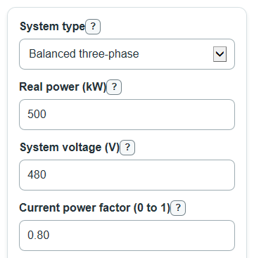
- Choose System type: Single-phase for one load circuit, or Balanced three-phase when the three lines carry about the same load.
- Enter Real power, System voltage, Current power factor, and Target power factor from your meter, bill, nameplate, or study data.
- Open Advanced options only if you need to change Frequency or choose a Three-phase capacitor connection of Wye or Delta.
- Select Calculate, then read Required capacitor bank size first and Equivalent capacitance per capacitor second.
- Sanity-check the results: Line current after target power factor should be lower than Line current before correction, and Target power factor must be higher than Current power factor.
Definitions
Power factor: A decimal from 0 to 1 that compares real working power with total AC power.
Real power: The useful power doing work, measured in kW.
Reactive power: The non-working AC power tied to magnetic or electric fields, measured in kVAR.
Apparent power: The total AC power demand seen by the supply, measured in kVA.
Required capacitor bank size: The total capacitor reactive power needed to raise the current lagging power factor to the target value.
Equivalent capacitance per capacitor: The uF value for each capacitor in the chosen single-phase, Wye, or Delta setup.
Wye: A three-phase capacitor connection with one capacitor from each line to a common point.
Delta: A three-phase capacitor connection with one capacitor across each pair of lines.
Line current: The current in a supply conductor, measured in amperes.
Common mistakes and quick fixes
Mistake: Entering motor horsepower instead of Real power.
Fix: Use Real power in kW from a meter, bill, drive, or converted load study value.
Mistake: Using line-to-neutral voltage for System voltage on a balanced three-phase load.
Fix: Enter the line-to-line System voltage for Balanced three-phase.
Mistake: Typing Current power factor as 80 instead of 0.80.
Fix: Enter Current power factor as a decimal from 0 to 1.
Mistake: Setting Target power factor lower than or equal to Current power factor.
Fix: Enter a Target power factor that is higher than Current power factor and no more than 1.00.
Mistake: Leaving Frequency at 60 Hz when the site uses 50 Hz.
Fix: Change Frequency to match the actual power system because it changes Equivalent capacitance per capacitor.
Mistake: Picking the wrong Three-phase capacitor connection.
Fix: Match Three-phase capacitor connection to the actual bank wiring because Wye and Delta give different uF per capacitor.
Limitations & Key Assumptions / Boundary Conditions
- This is a screening-level estimate for a lagging load. It does not replace an electrical design, code review, or utility approval.
- Balanced three-phase results assume the three lines carry about the same load. Unbalanced systems need phase-by-phase analysis.
- The model assumes sinusoidal steady-state power. Harmonics, resonance risk, detuned banks, and filter sizing are not checked.
- Capacitor switching steps, contactors, fuses, conductors, discharge resistors, enclosure ratings, and protection settings are outside this calculation.
- Real capacitor banks come in standard kVAR sizes and tolerances, so the installed size may differ from the calculated Required capacitor bank size.
- Over-correction can create a leading power factor. Check utility rules, equipment limits, and site load variation before installation.
Methodology
Power factor correction size
The calculator uses the common capacitor sizing method for raising a lagging power factor: find the reactive power before correction, find the reactive power allowed at the target power factor, then subtract the two values [1]. Power factor values are entered as decimals, such as 0.80 instead of 80 percent.
angle_current = arccos(current_pf)
angle_target = arccos(target_pf)
Q1 = real_power_kw * tan(angle_current)
Q2 = real_power_kw * tan(angle_target)
required_capacitor_bank_kvar = Q1 - Q2
Here Q1 is Reactive power before correction and Q2 is Reactive power remaining at target. The calculator requires Target power factor to be higher than Current power factor, so the required capacitor bank size is positive for a correction case.
kVA and line current
Apparent power is calculated from real power divided by power factor.
apparent_power_kva = real_power_kw / power_factor
For single-phase, the entered System voltage is the voltage across the load. For balanced three-phase, the entered System voltage is line-to-line voltage [2].
single_phase_current_a = apparent_power_kva * 1000 / system_voltage_v
three_phase_current_a = apparent_power_kva * 1000 / (sqrt(3) * system_voltage_v)
current_drop_percent = (line_current_before_a - line_current_after_target_a) / line_current_before_a * 100
Capacitance conversion
The capacitor bank kVAR is converted to uF using frequency, voltage, and the selected connection. Single-phase and balanced three-phase Wye use the same displayed formula when System voltage is line-to-line for the three-phase case.
capacitance_uf = required_kvar * 1000 * 1000000 / (2 * pi * frequency_hz * system_voltage_v^2)
For a balanced three-phase Delta bank, each capacitor is across line-to-line voltage and the three capacitors share the total kVAR.
capacitance_uf = required_kvar * 1000 * 1000000 / (3 * 2 * pi * frequency_hz * system_voltage_v^2)
Mini-example
For a 500 kW balanced three-phase load at 480 V, current power factor 0.80, target power factor 0.95, 60 Hz, and Wye connection: Q1 is 375.00 kVAR, Q2 is 164.34 kVAR, and Required capacitor bank size is 210.66 kVAR. Apparent power drops from 625.00 kVA to 526.32 kVA. Estimated line current drops from 751.76 A to 633.16 A. The equivalent Wye capacitance is 2425.29 uF per capacitor.