
Enter your three-phase conductor details to calculate line-to-line voltage drop, percent drop, and estimated voltage at the load.
Conductor information
Blank Advanced values use 1 equal conductor set per phase and a 3% planning target.
Advanced options
Table of contents
How to use our Three Phase Voltage Drop Calculator
- Choose "Simple wire estimate" when you know the conductor material and size, or choose "Detailed AC" when a cable data sheet provides resistance, reactance, power factor, and conductor temperature.
- Enter the line-to-line source voltage, load current, and one-way route length from the source to the load.
- For "Simple wire estimate," select the conductor material and size. For "Detailed AC," enter resistance and reactance in ohms per 1000 ft from the same cable-data source.
- Open "Advanced options" to change the number of equal parallel conductor sets, the planning target, or the displayed decimal places.
- Select "Calculate," then compare the percent drop with your planning target and confirm that the calculation basis matches the information you entered.
Definitions
Line-to-line voltage: Voltage measured between any two phases in a three-phase system.
One-way route length: The physical distance from the source to the load, measured once.
Power factor: A number from 0 through 1 used in the Detailed AC calculation to weight resistance and reactance.
Reactance: AC opposition from magnetic and electric fields in a wiring path. It can affect voltage drop when power factor is below 1.
Effective resistance: Resistance used in the calculation after the selected temperature and equal parallel sets are accounted for.
kcmil: One thousand circular mils, a conductor-area unit commonly used for large conductors.
Planning target: A percent-drop goal selected for comparison. It is not a universal electrical requirement.
Common mistakes and quick fixes
Mistake: Entering round-trip distance in "One-way route length (ft)."
Fix: Enter the physical source-to-load route once. The three-phase formula already accounts for the phase relationship.
Mistake: Using 120 V for a 120/208 V three-phase system.
Fix: Enter the voltage between phases: 208 V, not the 120 V line-to-neutral value.
Mistake: Entering DC resistance, ohms per mile, or ohms per km in a Detailed AC field.
Fix: Enter AC resistance and reactance in ohms per 1000 ft, or convert the cable data before entering it.
Mistake: Treating the 3% planning target as an automatic code pass.
Fix: Replace it with the applicable project or equipment requirement. This check does not test ampacity or code compliance.
Mistake: Entering a fractional number of parallel conductor sets.
Fix: Enter a whole number such as 1 or 2, and use more than 1 only for equal conductors that share current in parallel.
Limitations & Key Assumptions / Boundary Conditions
- This is a balanced three-phase, line-to-line estimate. It does not model unbalanced loads, harmonics, distributed loads, voltage regulation, or changing current along the route.
- "Simple wire estimate" uses conductor area, a 75 C resistance basis, unity power factor, and no separate reactance value.
- "Detailed AC" results depend on the entered cable resistance, reactance, power factor, conductor temperature, and assumption that parallel sets share current equally.
- The planning-target check compares voltage drop only. It does not determine ampacity, overcurrent protection, termination suitability, fault performance, or electrical code compliance.
- An extreme but mathematically valid input can produce a negative estimated load voltage. That indicates an unusable entered scenario, not a usable operating condition.
Methodology
Calculation method
The calculator uses the entered balanced three-phase line current and one-way route length. In "Simple wire estimate," it looks up the selected AWG or kcmil conductor area, applies the selected material's 75 C K factor, and assumes unity power factor.
R = K x 1000 / CM / P
R is effective resistance in ohms per 1000 ft, K is the material factor in ohm-cmil per ft, CM is conductor area in circular mils, and P is the number of equal parallel sets.
In "Detailed AC," the entered 75 C resistance is corrected to the entered conductor temperature, then divided by the number of equal parallel sets.
R = R75 x (C + T) / (C + 75) / P
R75 is the entered resistance at 75 C, C is the material temperature constant, and T is the entered conductor temperature in C. The calculation combines corrected resistance and reactance using power factor.
RF = √(1 - PF x PF)
Zc = R x PF + X x RF / P
PF is power factor, X is entered reactance in ohms per 1000 ft, RF is the reactive factor, and Zc is the impedance component used for voltage drop.
VD = √3 x I x L x Zc / 1000
Percent drop = VD / Vsource x 100
Vload = Vsource - VD
VD is line-to-line voltage drop in V, I is load current in A, L is one-way route length in ft, Vsource is entered line-to-line voltage, and Vload is estimated line-to-line voltage at the load.
Worked mini-example
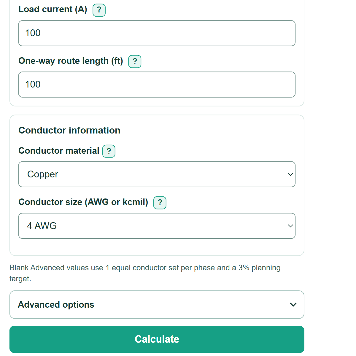
In the simple method, copper 4 AWG has 41,740 circular mils. At 100 A over 100 ft with one conductor set per phase, the estimate is 5.35 V of drop. With a 480 V source, that is 1.12% and leaves an estimated 474.65 V at the load.
The simple calculation is a resistance-only estimate at 75 C and unity power factor. The detailed calculation is only as accurate as the cable data and operating conditions entered. Voltage drop is separate from conductor sizing, ampacity, protection, and compliance checks.