
Estimate passive speaker crossover capacitor and inductor values for 2-way or 3-way DIY speakers from impedance and frequency.
Table of contents
How to use our Speaker Crossover Calculator
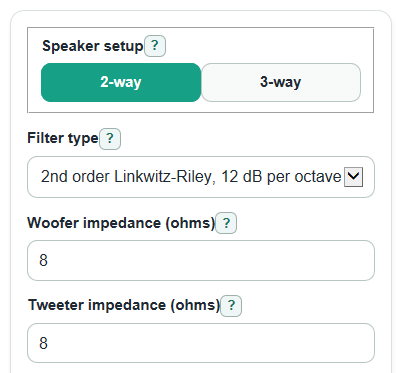
- Choose Speaker setup, then choose Filter type for the slope and part count you want to start with.
- Enter Woofer impedance, Tweeter impedance, and Crossover frequency for a 2-way speaker.
- For a 3-way speaker, enter Midrange impedance, Woofer to midrange frequency, and Midrange to tweeter frequency instead of the single Crossover frequency.
- Open Advanced options if you want E12 or E24 Standard part values, a rounding choice, and a Part tolerance check for real parts.
- Sanity-check the Parts to use: values should be in normal buyable ranges, and the 3-way spacing check should not warn unless you are ready to measure and tune the speaker.
Definitions
Passive crossover: A speaker filter made from parts such as capacitors and inductors between the amplifier and the drivers [1].
Crossover frequency: The frequency where one driver section starts handing sound to another driver section.
Impedance: The speaker driver's rated electrical load in ohms. The calculator uses it like a steady resistance for textbook crossover math.
Low-pass: A filter section that sends more low-frequency sound to a driver and reduces higher-frequency sound.
High-pass: A filter section that sends more high-frequency sound to a driver and reduces lower-frequency sound.
uF: Microfarads, the unit used here for capacitor values.
mH: Millihenrys, the unit used here for inductor values.
E12 and E24: Standard part value series used to pick nearby real capacitor and inductor values when the exact calculated value is not sold.
Common mistakes and quick fixes
Mistake: Entering the speaker box rating in Woofer impedance instead of the woofer driver rating.
Fix: Use the rated ohms printed for the woofer in Woofer impedance.
Mistake: Leaving Crossover frequency in kHz, such as entering 3 for a 3,000 Hz split.
Fix: Enter the full hertz value in Crossover frequency, such as 3000.
Mistake: In 3-way mode, making Midrange to tweeter frequency lower than Woofer to midrange frequency.
Fix: Set Midrange to tweeter frequency higher than Woofer to midrange frequency.
Mistake: Reading Woofer low-pass capacitor as needed for a 1st order filter.
Fix: For Filter type set to 1st order, use only the shown Woofer low-pass inductor and Tweeter high-pass capacitor.
Mistake: Treating Standard part values as a perfect match to the exact design value.
Fix: Check Nearest standard parts and its percent change before buying parts.
Mistake: Typing a negative Part tolerance or using it as a frequency adjustment.
Fix: Enter Part tolerance as a plus-or-minus percent printed on the part, such as 5 or 10.
Limitations & Key Assumptions / Boundary Conditions
- These are textbook passive crossover values, not a finished measured speaker design.
- The math treats each driver as a steady impedance at the crossover point. Real drivers change impedance with frequency.
- Driver response, acoustic offset, cabinet shape, baffle step, polarity, and part resistance can all change the final sound.
- 3-way results use a cascaded starting layout: woofer low-pass at the lower split, midrange band-pass between the splits, and tweeter high-pass at the upper split.
- A 3-way spacing ratio below 8 is allowed by the calculator, but it means the midrange band is narrower than about 3 octaves and needs extra care.
- Standard part rounding shows electrical value error only. It does not decide whether a nearby part sounds better in a real speaker.
- Part tolerance is a simple plus-or-minus value range. It does not include heat, aging, inductor core behavior, or capacitor type differences.
Methodology
How the values are calculated
The calculator uses common passive crossover equations for capacitor and inductor values. Capacitor and inductor values set the crossover frequency together with the driver impedance [2].
For a 1st order high-pass section, the tweeter or midrange capacitor is:
C_uF = 1000000 / (2 * pi * f_hz * R_ohms)
For a 1st order low-pass section, the woofer or midrange inductor is:
L_mH = 1000 * R_ohms / (2 * pi * f_hz)
For a 2nd order section, the calculator uses filter constants:
C_uF = 1000000 * Kc / (R_ohms * f_hz)
L_mH = 1000 * Kl * R_ohms / f_hz
For 2nd order Butterworth, Kc is 0.1125395395 and Kl is 0.2250790790. For 2nd order Linkwitz-Riley, Kc is 0.0795774715 and Kl is 0.3183098862.
2-way and 3-way mapping
In 2-way mode, the woofer uses a low-pass section at Crossover frequency, and the tweeter uses a high-pass section at Crossover frequency. In 3-way mode, the woofer low-pass and midrange lower high-pass use Woofer to midrange frequency. The midrange upper low-pass and tweeter high-pass use Midrange to tweeter frequency.
The 3-way spacing check is:
spacing_ratio = upper_crossover_hz / lower_crossover_hz
A ratio under 8 still calculates, but the result is marked because the two crossover points are close for a simple textbook 3-way starting point.
Standard parts
If E12 or E24 Standard part values are selected, the calculator compares each exact uF or mH value with the selected preferred-value series across powers of 10. It can choose the nearest, next lower, or next higher value.
The signed part error is:
part_error_percent = 100 * (standard_value - exact_value) / exact_value
A positive error means the selected standard part is higher than the exact value. A negative error means it is lower.
Mini-example
For a 2-way speaker with 8 ohm woofer impedance, 8 ohm tweeter impedance, a 3000 Hz crossover frequency, and a 2nd order Linkwitz-Riley filter, the exact values are 0.8488 mH for the woofer low-pass inductor, 3.3157 uF for the woofer low-pass capacitor, 3.3157 uF for the tweeter high-pass capacitor, and 0.8488 mH for the tweeter high-pass inductor.