
Enter your 555 timer parts to calculate oscillator frequency or pulse width, or find a timing resistor or capacitor for your design.
Nearest E24 nominal value to the ideal resistance.
Use this with the recommended R1 and preferred capacitor.
Table of contents
How to use our 555 Timer Calculator
- Choose what you want to calculate: astable timing from parts, monostable pulse width, a needed monostable resistor or capacitor, or astable target design.
- Enter values from your schematic, parts list, component markings, or project requirement, and choose the unit printed with each value.
- Click Calculate to see the main frequency, time, resistance, or capacitance first, followed by supporting timing values when they apply.
- For astable target design, enter a frequency above 0, a high-time share above 50% and below 100%, and a capacitor value you can use.
- Sanity-check the result: increasing a timing resistor or capacitor should make the timing longer, and a longer astable period means a lower frequency.
Definitions
Astable: A 555 circuit that repeatedly switches its output high and low. It acts as an oscillator.
Monostable: A 555 circuit that produces one output pulse after a trigger. It is also called a one-shot.
R1 and R2: The two timing resistors in the standard astable circuit. R1 affects charging time, while R2 affects both charging and discharging time.
Timing capacitor: The capacitor that charges and discharges to set a time interval.
Frequency: The number of complete cycles per second, measured in hertz (Hz).
Period: The time for one complete high-and-low cycle. It is the reciprocal of frequency.
High-time share: The percent of one astable cycle during which the output is high. It is also called duty cycle.
E24 values: Preferred nominal component values repeated across powers of ten. The target-design calculation uses nearby E24 resistor values as practical starting choices.
Common mistakes and quick fixes
Mistake: Entering 10 for a resistor while its unit is set to Ohm instead of kOhm.
Fix: Match the prefix on the schematic or part label. For 10 kOhm, enter 10 and choose kOhm.
Mistake: Swapping R1 and R2 in an astable circuit.
Fix: Enter R1 for the resistor from the supply to the discharge pin. Enter R2 for the resistor from the discharge pin to the timing capacitor.
Mistake: Using zero or a negative resistance, capacitance, frequency, or pulse width.
Fix: Enter a finite positive number greater than 0 for every value shown in the selected calculation.
Mistake: Requesting a 50% or lower high-time share in the standard two-resistor astable circuit.
Fix: Enter a value above 50% and below 100%, or use a modified circuit that supports a lower duty cycle.
Mistake: Treating an E24 resistor recommendation as the exact ideal resistance.
Fix: Use the recalculated frequency and high-time share, then measure the completed circuit if timing accuracy matters.
Limitations & Key Assumptions / Boundary Conditions
- Results use ideal standard 555 timing equations and do not include resistor or capacitor tolerance, capacitor leakage, temperature, output loading, supply noise, or differences among 555 device versions.
- The standard two-resistor astable model requires positive R1 and R2 values and produces a high-time share above 50%. A target of 50% or less needs a different circuit arrangement.
- Astable target design rounds each ideal resistor independently to a nominal E24 value, so the recalculated frequency and high-time share can differ from the target.
- Capacitors, especially larger-value types, can have substantial tolerance and leakage. Measure the completed circuit when timing accuracy is important.
- Supply voltage is not included because it is not part of these ideal timing equations, but poor supply conditions or wiring can still affect a real circuit.
Methodology
How the timing is calculated
The calculator converts resistance to ohms, capacitance to farads, time to seconds, and frequency to hertz before applying the ideal equation for the selected circuit.
T (period in seconds) = ln(2) * C (capacitance in farads) * (R1 + 2 * R2)
For a standard astable circuit, ln(2) is the natural logarithm of 2. Frequency is the reciprocal of period.
f (frequency in Hz) = 1 / T
The calculator also separates the high and low parts of each astable cycle.
t_high (high time in seconds) = ln(2) * C * (R1 + R2)
t_low (low time in seconds) = ln(2) * C * R2
high-time share (percent) = 100 * (R1 + R2) / (R1 + 2 * R2)
For a monostable circuit, the ideal pulse width uses the nominal 1.1 timing factor. Rearranging that relationship gives the needed resistor or capacitor.
pulse width (seconds) = 1.1 * R (ohms) * C (farads)
R (ohms) = pulse width / (1.1 * C)
C (farads) = pulse width / (1.1 * R)
Astable target design
Target design uses the wanted frequency, high-time share, and chosen capacitor to calculate ideal R1 and R2 values. A high-time share of 50% or less is rejected because the standard positive-resistor circuit would require R1 to be zero or negative. Each positive ideal resistance is matched to the nearest nominal E24 value, with an exact tie going to the lower value. The calculator then recalculates frequency, period, high time, low time, and high-time share from those nominal resistors.
Worked example
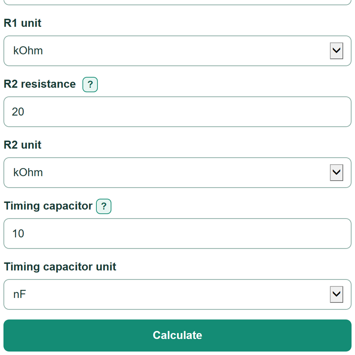
With R1 = 10 kOhm, R2 = 20 kOhm, and C = 10 nF, the resistance term is 10,000 + 2 * 20,000 = 50,000 ohms.
T = 0.6931471805599453 * 0.00000001 * 50000 = 0.00034657359028 s
f = 1 / 0.00034657359028 = approximately 2885.39 Hz
The ideal high time is approximately 207.94 microseconds, the low time is approximately 138.63 microseconds, and the high-time share is 60%.